9.2 Multimedia Applications
Just like the traditional applications described in the previous
section, multimedia applications such as telephony and videoconferencing
need their own protocols. Much of the initial experience in designing
protocols for multimedia applications came from the MBone
tools—applications such as vat and vic that were developed for
use on the MBone, an overlay network that supports IP multicast to
enable multiparty conferencing. (More on overlay networks including the
MBone in the next section.) Initially, each application implemented its
own protocol (or protocols), but it became apparent that many multimedia
applications have common requirements. This ultimately led to the
development of a number of general-purpose protocols for use by
multimedia applications.
We have already seen a number of protocols that multimedia applications use. The Real-Time Transport Protocol (RTP) provides many of the functions that are common to multimedia applications such as conveying timing information and identifying the coding schemes and media types of an application.
The Resource Reservation Protocol (RSVP) can be used to request the allocation of resources in the network so that the desired quality of service (QoS) can be provided to an application. We will see how resource allocation interacts with other aspects of multimedia applications later in this section.
In addition to these protocols for multimedia transport and resource allocation, many multimedia applications also need a signalling or session control protocol. For example, suppose that we wanted to be able to make telephone calls across the Internet (Voice over IP, or VoIP). We would need some mechanism to notify the intended recipient of such a call that we wanted to talk to her, such as by sending a message to some multimedia device that would cause it to make a ringing sound. We would also like to be able to support features like call forwarding, three-way calling, etc. The Session Initiation Protocol (SIP) and H.323 are examples of protocols that address the issues of session control; we begin our discussion of multimedia applications by examining these protocols.
9.2.1 Session Control and Call Control (SDP, SIP, H.323)
To understand some of the issues of session control, consider the following problem. Suppose you want to hold a videoconference at a certain time and make it available to a wide number of participants. Perhaps you have decided to encode the video stream using the MPEG-2 standard, to use the multicast IP address 224.1.1.1 for transmission of the data, and to send it using RTP over UDP port number 4000. How would you make all that information available to the intended participants? One way would be to put all that information in an email and send it out, but ideally there should be a standard format and protocol for disseminating this sort of information. The IETF has defined protocols for just this purpose. The protocols that have been defined include
Session Description Protocol (SDP)
Session Announcement Protocol (SAP)
Session Initiation Protocol (SIP)
Simple Conference Control Protocol (SCCP)
You might think that this is a lot of protocols for a seemingly simple task, but there are many aspects of the problem and several different situations in which it must be addressed. For example, there is a difference between announcing the fact that a certain conference session is going to be made available on the MBone (which would be done using SDP and SAP) and trying to make an Internet phone call to a certain user at a particular time (which could be done using SDP and SIP). In the former case, you could consider your job done once you have sent all the session information in a standard format to a well-known multicast address. In the latter, you would need to locate one or more users, get a message to them announcing your desire to talk (analogous to ringing their phone), and perhaps negotiate a suitable audio encoding among all parties. We will look first at SDP, which is common to many applications, then at SIP, which is widely used for a number of interactive applications such as Internet telephony.
Session Description Protocol (SDP)
The Session Description Protocol (SDP) is a rather general protocol that can be used in a variety of situations and is typically used in conjunction with one or more other protocols (e.g., SIP). It conveys the following information:
The name and purpose of the session
Start and end times for the session
The media types (e.g., audio, video) that comprise the session
Detailed information required to receive the session (e.g., the multicast address to which data will be sent, the transport protocol to be used, the port numbers, the encoding scheme)
SDP provides this information formatted in ASCII using a sequence of
lines of text, each of the form <type>=<value>. An example of an SDP
message will illustrate the main points.
v=0
o=larry 2890844526 2890842807 IN IP4 128.112.136.10
s=Networking 101
i=A class on computer networking
u=http://www.cs.princeton.edu/
e=larry@cs.princeton.edu
c=IN IP4 224.2.17.12/127
t=2873397496 2873404696
m=audio 49170 RTP/AVP 0
m=video 51372 RTP/AVP 31
m=application 32416 udp wb
Note that SDP, like HTML, is fairly easy for a human to read but has strict formatting rules that make it possible for machines to interpret the data unambiguously. For example, the SDP specification defines all the possible information types that are allowed to appear, the order in which they must appear, and the format and reserved words for every type that is defined.
The first thing to notice is that each information type is identified by
a single character. For example, the line tells us that “version” has
the value zero; that is, this message is formatted according to version
zero of SDP. The next line provides the “origin” of the session which
contains enough information to uniquely identify the session. larry
is a username of the session creator, and 128.112.136.10 is the IP
address of his computer. The number following larry is a session
identifier that is chosen to be unique to that machine. This is followed
by a “version” number for the SDP announcement; if the session information
was updated by a later message, the version number would be increased.
The next three lines (i, s and u) provide the session name,
a session description, and a session Uniform Resource Identifier (URI,
as described earlier in this chapter)—information that would be helpful
to a user in deciding whether to participate in this session. Such
information could be displayed in the user interface of a session
directory tool that shows current and upcoming events that have been
advertised using SDP. The next line (e=...) contains an email
address of a person to contact regarding the session. Figure 222 shows a screen shot of a (now archaic) session
directory tool called sdr along with the descriptions of several
sessions that had been announced at the time the picture was taken.
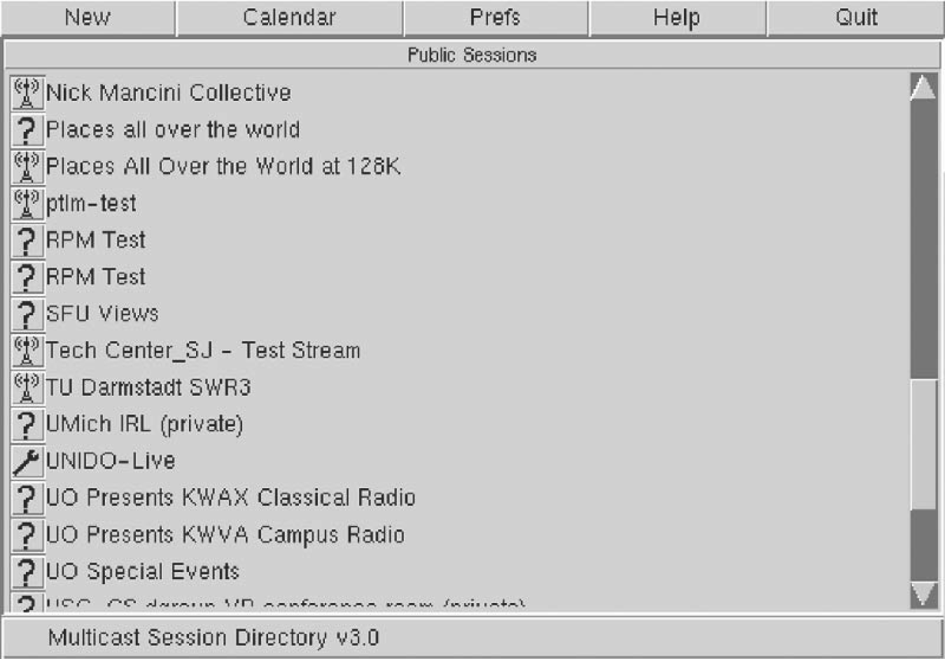
Figure 222. A session directory tool displays information extracted from SDP messages.
Next we get to the technical details that would enable an application
program to participate in the session. The line beginning c=...
provides the IP multicast address to which data for this session will be
sent; a user would need to join this multicast group to receive the
session. Next we see the start and end times for the session (encoded as
integers according to the Network Time Protocol). Finally, we get to the
information about the media for this session. This session has three
media types available—audio, video, and a shared whiteboard application
known as wb. For each media type there is one line of information
formatted as follows:
m=<media> <port> <transport> <format>
The media types are self-explanatory, and the port numbers in each case
are UDP ports. When we look at the “transport” field, we can see that
the wb application runs directly over UDP, while the audio and video
are transported using “RTP/AVP”. This means that they run over RTP and
use the application profile known as AVP. That application profile
defines a number of different encoding schemes for audio and video; we
can see in this case that the audio is using encoding 0 (which is an
encoding using an 8-kHz sampling rate and 8 bits per sample) and the
video is using encoding 31, which represents the H.261 encoding scheme.
These “magic numbers” for the encoding schemes are defined in the RFC
that defines the AVP profile; it is also possible to describe
nonstandard coding schemes in SDP.
Finally, we see a description of the “wb” media type. All the encoding
information for this data is specific to the wb application, and so
it is sufficient just to provide the name of the application in the
“format” field. This is analogous to putting application/wb in a
MIME message.
Now that we know how to describe sessions, we can look at how they can be initiated. One way in which SDP is used is to announce multimedia conferences, by sending SDP messages to a well-known multicast address. The session directory tool shown in Figure 222 would function by joining that multicast group and displaying information that it gleans from received SDP messages. SDP is also used in the delivery of entertainment video of IP (often called IPTV) to provide information about the video content on each TV channel.
SDP also plays an important role in conjunction with the Session Initiation Protocol (SIP). With the widespread adoption of Voice over IP (i.e., the support of telephony-like applications over IP networks) and IP-based video conferencing, SIP is now one of the more important members of the Internet protocol suite.
SIP
SIP is an application layer protocol that bears a certain resemblance to HTTP, being based on a similar request/response model. However, it is designed with rather different sorts of applications in mind and thus provides quite different capabilities than HTTP. The capabilities provided by SIP can be grouped into five categories:
User location—Determining the correct device with which to communicate to reach a particular user
User availability—Determining if the user is willing or able to take part in a particular communication session
User capabilities—Determining such items as the choice of media and coding scheme to use
Session setup—Establishing session parameters such as port numbers to be used by the communicating parties
Session management—A range of functions including transferring sessions (e.g., to implement “call forwarding”) and modifying session parameters
Most of these functions are easy enough to understand, but the issue of location bears some further discussion. One important difference between SIP and, say, HTTP, is that SIP is primarily used for human-to-human communication. Thus, it is important to be able to locate individual users, not just machines. And, unlike email, it’s not good enough just to locate a server that the user will be checking on at some later date and dump the message there—we need to know where the user is right now if we want to be able to communicate with him in real time. This is further complicated by the fact that a user might choose to communicate using a range of different devices, such as using his desktop PC when he’s in the office and using a handheld device when traveling. Multiple devices might be active at the same time and might have widely different capabilities (e.g., an alphanumeric pager and a PC-based video “phone”). Ideally, it should be possible for other users to be able to locate and communicate with the appropriate device at any time. Furthermore, the user must be able to have control over when, where, and from whom he receives calls.
To enable a user to exercise the appropriate level of control over his calls, SIP introduces the notion of a proxy. A SIP proxy can be thought of as a point of contact for a user to which initial requests for communication with him are sent. Proxies also perform functions on behalf of callers. We can see how proxies work best through an example.
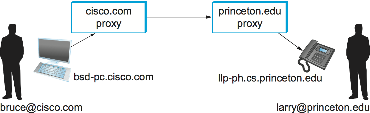
Figure 223. Establishing communication through SIP proxies.
Consider the two users in Figure 223. The
first thing to notice is that each user has a name in the format
user@domain, very much like an email address. When user Bruce
wants to initiate a session with Larry, he sends his initial SIP
message to the local proxy for his domain, cisco.com. Among other
things, this initial message contains a SIP URI—these are a form of
uniform resource identifier which look like this:
SIP:larry@princeton.edu
A SIP URI provides complete identification of a user, but (unlike a URL) does not provide his location, since that may change over time. We will see shortly how the location of a user can be determined.
Upon receiving the initial message from Bruce, the proxy looks at the SIP URI and deduces that this message should be sent to the proxy. For now, we assume that the proxy has access to some database that enables it to obtain a mapping from the name to the IP address of one or more devices at which Larry currently wishes to receive messages. The proxy can therefore forward the message on to Larry’s chosen device(s). Sending the message to more than one device is called forking and may be done either in parallel or in series (e.g., send it to his mobile phone if he doesn’t answer the phone at his desk).
The initial message from Bruce to Larry is likely to be a SIP invite
message, which looks something like the following:
INVITE sip:larry@princeton.edu SIP/2.0
Via: SIP/2.0/UDP bsd-pc.cisco.com;branch=z9hG4bK433yte4
To: Larry <sip:larry@princeton.edu>
From: Bruce <sip:bruce@cisco.com>;tag=55123
Call-ID: xy745jj210re3@bsd-pc.cisco.com
CSeq: 271828 INVITE
Contact: <sip:bruce@bsd-pc.cisco.com>
Content-Type: application/sdp
Content-Length: 142
The first line identifies the type of function to be performed
(invite); the resource on which to perform it, the called party
(sip:larry@princeton.edu ); and the protocol version (2.0). The
subsequent header lines probably look somewhat familiar because of
their resemblance to the header lines in an email message. SIP defines
a large number of header fields, only some of which we describe
here. Note that the Via: header in this example identifies the
device from which this message originated. The Content-Type: and
Content-Length: headers describe the contents of the message
following the header, just as in a MIME-encoded email message. In this
case, the content is an SDP message. That message would describe such
things as the type of media (audio, video, etc.) that Bruce would like
to exchange with Larry and other properties of the session such as
codec types that he supports. Note that the field in SIP provides the
capability to use any protocol for this purpose, although SDP is the
most common.
Returning to the example, when the invite message arrives at the
proxy, not only does the proxy forward the message on toward
princeton.edu, but it also responds to the sender of the invite.
Just as in HTTP, all responses have a response code, and the
organization of codes is similar to that for HTTP. In Figure 224 we can see a sequence of SIP messages and responses.
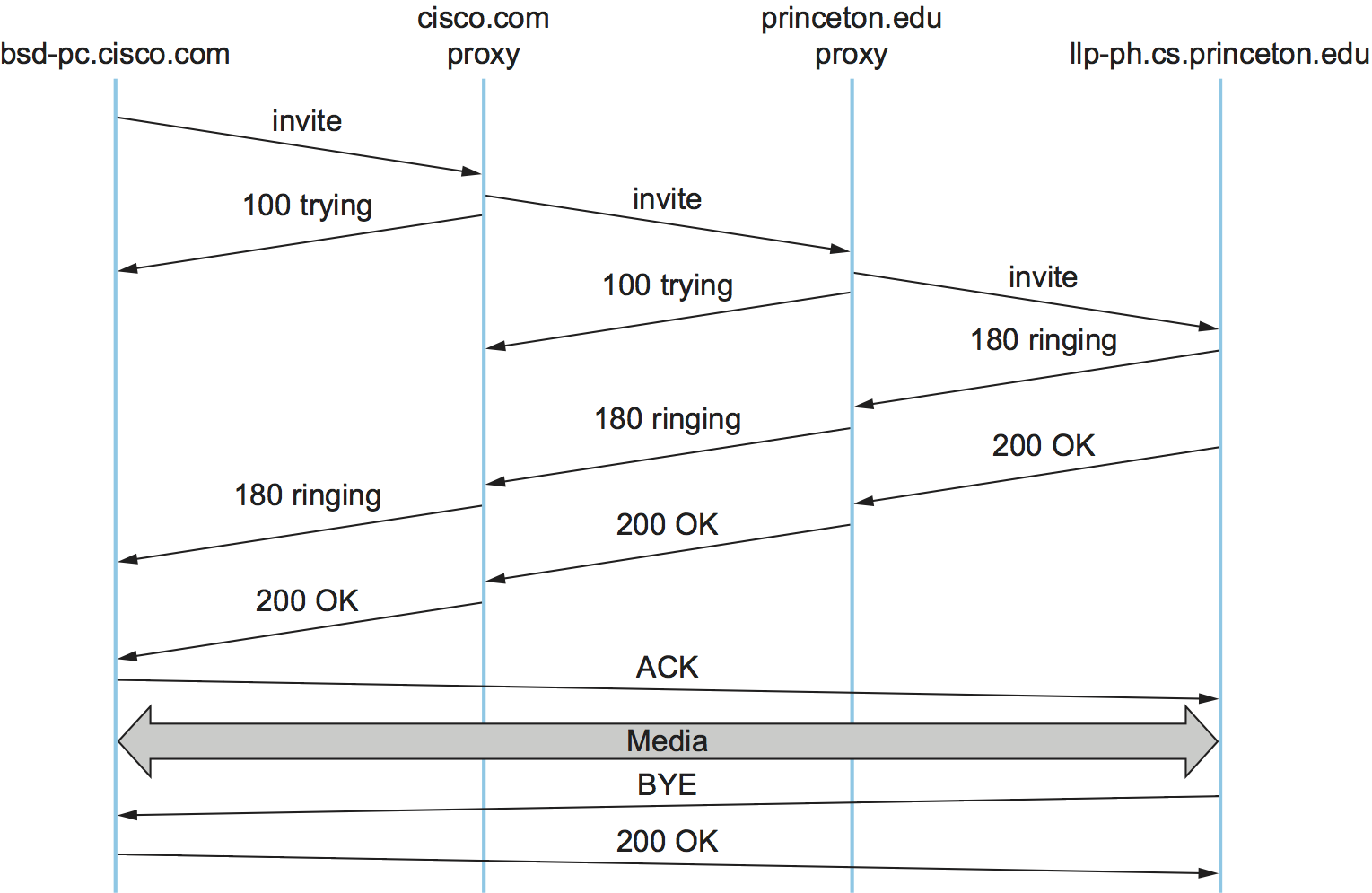
Figure 224. Message flow for a basic SIP session.
The first response message in this figure is the provisional response
100 trying, which indicates that the message was received without
error by the caller’s proxy. Once the invite is delivered to Larry’s
phone, it alerts Larry and responds with a 180 ringing message. The
arrival of this message at Bruce’s computer is a sign that it can
generate a “ringtone”. Assuming Larry is willing and able to communicate
with Bruce, he could pick up his phone, causing the message 200 OK
to be sent. Bruce’s computer responds with an ACK, and media (e.g.,
an RTP-encapsulated audio stream) can now begin to flow between the two
parties. Note that at this point the parties know each others’
addresses, so the ACK can be sent directly, bypassing the proxies.
The proxies are now no longer involved in the call. Note that the media
will therefore typically take a different path through the network than
the original signalling messages. Furthermore, even if one or both of
the proxies were to crash at this point, the call could continue on
normally. Finally, when one party wishes to end the session, it sends a
BYE message, which elicits a 200 OK response under normal
circumstances.
There are a few details that we have glossed over. One is the
negotiation of session characteristics. Perhaps Bruce would have liked
to communicate using both audio and video but Larry’s phone only
supports audio. Thus, Larry’s phone would send an SDP message in its
200 OK describing the properties of the session that will be
acceptable to Larry and the device, considering the options that were
proposed in Bruce’s invite. In this way, mutually acceptable session
parameters are agreed to before the media flow starts.
The other big issue we have glossed over is that of locating the correct
device for Larry. First, Bruce’s computer had to send its invite to
the cisco.com proxy. This could have been a configured piece of
information in the computer, or it could have been learned by DHCP. Then
the cisco.com proxy had to find the princeton.edu proxy. This
could be done using a special sort of DNS lookup that would return the
IP address of the SIP proxy for the domain. (We’ll discuss how DNS can
do this in the next section.) Finally, the princeton.edu proxy had to
find a device on which Larry could be contacted. Typically, a proxy
server has access to a location database that can be populated in
several ways. Manual configuration is one option, but a more flexible
option is to use the registration capabilities of SIP.
A user can register with a location service by sending a SIP
register message to the “registrar” for his domain. This message
creates a binding between an “address of record” and a “contact
address”. An “address of record” is likely to be a SIP URI that is the
well-known address for the user (e.g., sip:larry@princeton.edu) and
the “contact address” will be the address at which the user can
currently be found (e.g., sip:larry@llp-ph.cs.princeton.edu). This
is exactly the binding that was needed by the proxy princeton.edu in
our example.
Note that a user may register at several locations and that multiple users may register at a single device. For example, one can imagine a group of people walking into a conference room that is equipped with an IP phone and all of them registering on it so that they can receive calls on that phone.
SIP is a very rich and flexible protocol that can support a wide range of complex calling scenarios as well as applications that have little or nothing to do with telephony. For example, SIP supports operations that enable a call to be routed to a “music-on-hold” server or a voicemail server. It is also easy to see how it could be used for applications like instant messaging, and standardization of SIP extensions for such purposes is ongoing.
H.323
The International Telecommunication Union (ITU) has also been very active in the call control area, which is not surprising given its relevance to telephony, the traditional realm of that body. Fortunately, there has been considerable coordination between the IETF and the ITU in this instance, so that the various protocols are somewhat interoperable. The major ITU recommendation for multimedia communication over packet networks is known as H.323, which ties together many other recommendations, including H.225 for call control. The full set of recommendations covered by H.323 runs to many hundreds of pages, and the protocol is known for its complexity, so it is only possible to give a brief overview of it here.
H.323 is popular as a protocol for Internet telephony, including video calls, and we consider that class of application here. A device that originates or terminates calls is known as an H.323 terminal; this might be a workstation running an Internet telephony application, or it might be a specially designed “appliance”—a telephone-like device with networking software and an Ethernet port, for example. H.323 terminals can talk to each other directly, but the calls are frequently mediated by a device known as a gatekeeper. Gatekeepers perform a number of functions such as translating among the various address formats used for phone calls and controlling how many calls can be placed at a given time to limit the bandwidth used by the H.323 applications. H.323 also includes the concept of a gateway, which connects the H.323 network to other types of networks. The most common use of a gateway is to connect an H.323 network to the public switched telephone network (PSTN) as illustrated in Figure 225. This enables a user running an H.323 application on a computer to talk to a person using a conventional phone on the public telephone network. One useful function performed by the gatekeeper is to help a terminal find a gateway, perhaps choosing among several options to find one that is relatively close to the ultimate destination of the call. This is clearly useful in a world where conventional phones greatly outnumber PC-based phones. When an H.323 terminal makes a call to an endpoint that is a conventional phone, the gateway becomes the effective endpoint for the H.323 call and is responsible for performing the appropriate translation of both signalling information and the media stream that need to be carried over the telephone network.
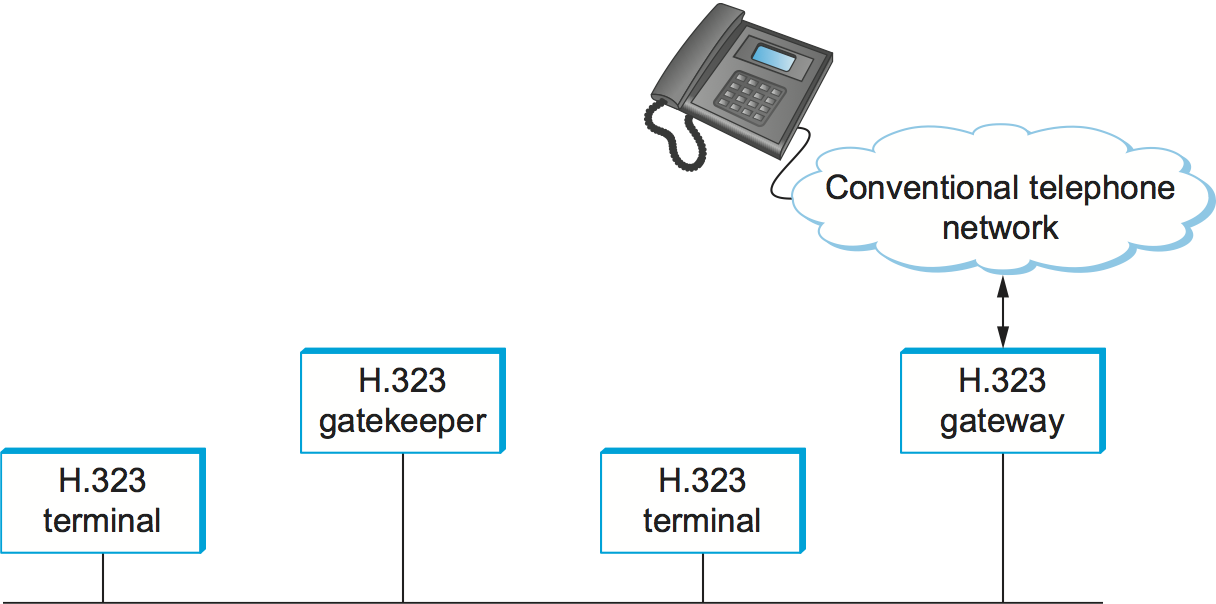
Figure 225. Devices in an H.323 network.
An important part of H.323 is the H.245 protocol, which is used to negotiate the properties of the call, somewhat analogously to the use of SDP described above. H.245 messages might list a number of different audio codec standards that it can support; the far endpoint of the call would reply with a list of its own supported codecs, and the two ends could pick a coding standard that they can both live with. H.245 can also be used to signal the UDP port numbers that will be used by RTP and Real-Time Control Protocol (RTCP) for the media stream (or streams—a call might include both audio and video, for example) for this call. Once this is accomplished, the call can proceed, with RTP being used to transport the media streams and RTCP carrying the relevant control information.
9.2.2 Resource Allocation for Multimedia Applications
As we have just seen, session control protocols like SIP and H.323 can be used to initiate and control communication in multimedia applications, while RTP provides transport-level functions for the data streams of the applications. A final piece of the puzzle in getting multimedia applications to work is making sure that suitable resources are allocated inside the network to ensure that the quality of service needs of the application are met. We presented a number of methods for resource allocation in an earlier chapter. The motivation for developing these technologies was largely for the support of multimedia applications. So how do applications take advantage of the underlying resource allocation capabilities of the network?
It is worth noting that many multimedia applications run successfully over “best-effort” networks, such as the public Internet. The wide array of commercial VoIP services (such as Skype) are a testimony to the fact that you only have to worry about resource allocation when resources are not abundant—and in many parts of today’s Internet, resource abundance is the norm.
A protocol like RTCP can help applications in best-effort networks, by giving the application detailed information about the quality of service that is being delivered by the network. Recall that RTCP carries information about the loss rate and delay characteristics between participants in a multimedia application. An application can use this information to change its coding scheme—changing to a lower bitrate codec, for example, when bandwidth is scarce. Note that, while it might be tempting to change to a codec that sends additional, redundant information when loss rates are high, this is frowned upon; it is analogous to increasing the window size of TCP in the presence of loss, the exact opposite of what is required to avoid congestion collapse.
As discussed in an earlier chapter, Differentiated Services (DiffServ) can be used to provide fairly basic and scalable resource allocation to applications. A multimedia application can set the differentiated services code point (DSCP) in the IP header of the packets that it generates in an effort to ensure that both the media and control packets receive appropriate quality of service. For example, it is common to mark voice media packets as “EF” (expedited forwarding) to cause them to be placed in a low-latency or priority queue in routers along the path, while the call signalling (e.g., SIP) packets are often marked with some sort of “AF” (assured forwarding) to enable them to be queued separately from best-effort traffic and thus reduce their risk of loss.
Of course, it only makes sense to mark the packets inside the sending host or appliance if network devices such as routers pay attention to the DSCP. In general, routers in the public Internet ignore the DSCP, providing best-effort service to all packets. However, enterprise or corporate networks have the ability to use DiffServ for their internal multimedia traffic, and frequently do so. Also, even residential users of the Internet can often improve the quality of VoIP or other multimedia applications just by using DiffServ on the outbound direction of their Internet connections, as illustrated in Figure 226. This is effective because of the asymmetry of many broadband Internet connections: If the outbound link is substantially slower (i.e., more resource constrained) than the inbound, then resource allocation using DiffServ on that link may be enough to make all the difference in quality for latency- and loss-sensitive applications.
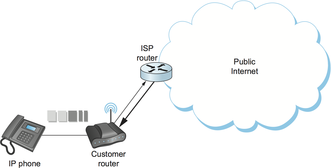
Figure 226. Differentiated Services applied to a VoIP application. DiffServ queuing is applied only on the upstream link from customer router to ISP.
While DiffServ is appealing for its simplicity, it is clear that it cannot meet the needs of applications under all conditions. For example, suppose the upstream bandwidth in Figure 226 is only 100 kbps, and the customer attempts to place two VoIP calls, each with a 64-kbps codec. Clearly the upstream link is now more than 100% loaded, which will lead to large queuing delays and lost packets. No amount of clever queuing in the customer’s router can fix that.
The characteristics of many multimedia applications are such that, rather than try to squeeze too many calls into a too-narrow pipe, it would be better to block one call while allowing another to proceed. That is, it is better to have one person carrying on a conversation successfully while another hears a busy signal than to have both callers experiencing unacceptable audio quality at the same time. We sometimes refer to such applications as having a steep utility curve, meaning that the utility (usefulness) of the application drops rapidly as the quality of service provided by the network degrades. Multimedia applications often have this property, whereas many traditional applications do not. Email, for example, continues to work quite well even if delays run into the hours.
Applications with steep utility curves are often well suited to some form of admission control. If you cannot be sure that sufficient resources will always be available to support the offered load of the applications, then admission control provides a way to say “no” to some applications while allowing others to get the resources they need.
We saw one way to do admission control using RSVP in an earlier chapter, and we will return to that shortly, but multimedia applications that use session control protocols provide some other admission control options. The key point to observe here is that session control protocols like SIP or H.323 often involve some sort of message exchange between an endpoint and another entity (SIP proxy or H.323 gatekeeper) at the beginning of a call or session. This can provide a handy means to say “no” to a new call for which sufficient resources are not available.
As an example, consider the network in Figure 227. Suppose the wide area link from the branch office to the head office has enough bandwidth to accommodate three VoIP calls simultaneously using 64-kbps codecs. Each phone already needs to communicate with the local SIP proxy or H.323 gatekeeper when it begins to place a call, so it is easy enough for the proxy/gatekeeper to send back a message that tells the IP phone to play a busy signal if that link is already fully loaded. The proxy or gatekeeper can even deal with the possibility that a particular IP phone might be making multiple calls at the same time and that different codec speeds might be used. However, this scheme will work only if no other device can overload the link without first talking to the gatekeeper or proxy. DiffServ queuing can be used to ensure that, for example, a PC engaged in a file transfer doesn’t interfere with the VoIP calls. But, suppose some VoIP application that doesn’t first talk to the gatekeeper or proxy is enabled in the remote office. Such an application, if it can get its packets marked appropriately and in the same queue as the existing VoIP traffic, can clearly drive the link to the point of overload with no feedback from the proxy or gatekeeper.
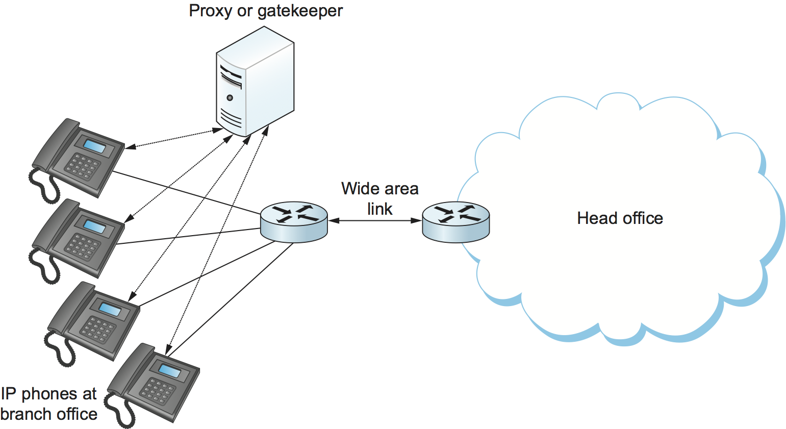
Figure 227. Admission control using session control protocol.
Another problem with the approach just described is that it depends on the gatekeeper or proxy having knowledge of the path that each application will use. In the simple topology of Figure 227 this isn’t a big issue, but in more complex networks it can quickly become unmanageable. We only need to imagine the case where the remote office has two different connections to the outside world to see that we are asking the proxy or gatekeeper to understand not just SIP or H.323 but also routing, link failures, and current network conditions. This can quickly become unmanageable.
We refer to the sort of admission control just described as off-path, in the sense that the device making admission control decisions does not sit on the data path where resources need to be allocated. The obvious alternative is on-path admission control, and the standard example of a protocol that does on-path admission control in IP networks is the Resource Reservation Protocol (RSVP). We saw in an earlier chapter how RSVP can be used to ensure that sufficient resources are allocated along a path, and it is straightforward to use RSVP in applications like those described in this section. The one detail that still needs to be filled in is how the admission control protocol interacts with the session control protocol.
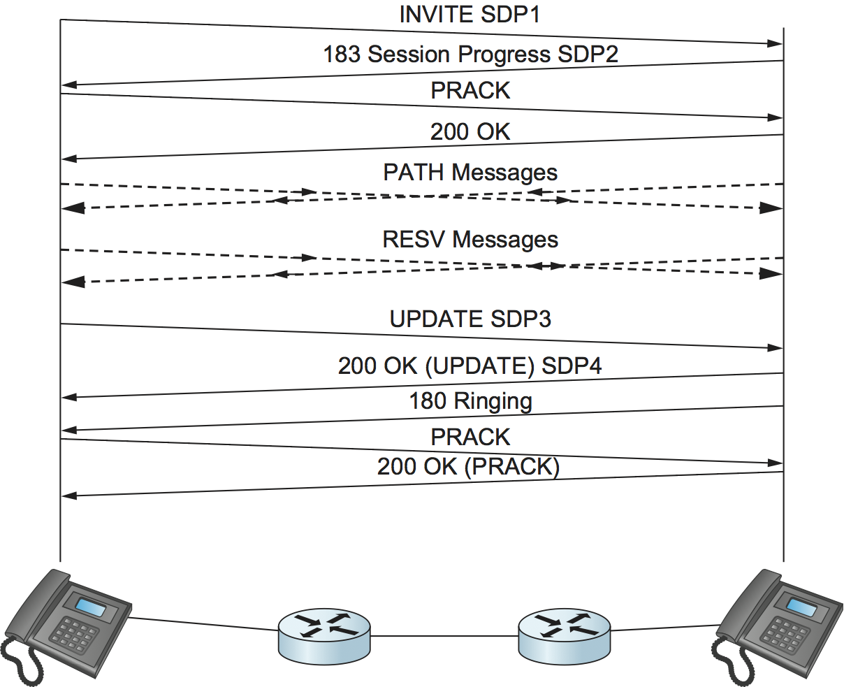
Figure 228. Coordination of SIP signalling and resource reservation.
Coordinating the actions of an admission control (or resource reservation) protocol and a session control protocol is not rocket science, but it does require some attention to details. As an example, consider a simple telephone call between two parties. Before you can make a reservation, you need to know how much bandwidth the call is going to use, which means you need to know what codecs are to be used. That implies you need to do some of the session control first, to exchange information about the codecs supported by the two phones. However, you can’t do all the session control first, because you wouldn’t want the phone to ring before the admission control decision had been made, in case admission control failed. Figure 228 illustrates this situation where SIP is used for session control and RSVP is used to make the admission control decision (successfully in this case).
The main thing to notice here is the interleaving of session control and resource allocation tasks. Solid lines represent SIP messages, dashed lines represent RSVP messages. Note that SIP messages are transmitted direction from phone to phone in this example (i.e., we have not shown any SIP proxies), whereas the RSVP messages are also processed by the routers in the middle as the check for sufficient resources to admit the call.
We begin with an initial exchange of codec information in the first two
SIP messages (recall that SDP is used to list available codecs, among
other things). PRACK is a “provisional acknowledgment”. Once these
messages have been exchanged, RSVP PATH messages, which contain a
description of the amount of resources that will be required, can be
sent as the first step in reserving resources in both directions of the
call. Next, RESV messages can be sent back to actually reserve the
resources. Once a RESV is received by the initiating phone, it can
send an updated SDP message reporting the fact that resources have been
reserved in one direction. When the called phone has received both that
message and the RESV from the other phone, it can start to ring and
tell the other phone that resources are now reserved in both directions
(with the SDP message) and also notify the calling phone that it is
ringing. From here on, normal SIP signalling and media flow, similar to
that shown in Figure 224, proceeds.
Again we see how building applications requires us to understand the interaction between different building blocks (SIP and RSVP, in this case). The designers of SIP actually made some changes to the protocol to enable this interleaving of functions between protocols with different jobs, hence our repeated emphasis in this book on focusing on complete systems rather than just looking at one layer or component in isolation from the other parts of the system.