3.4 Routing
So far in this chapter we have assumed that the switches and routers have enough knowledge of the network topology so they can choose the right port onto which each packet should be output. In the case of virtual circuits, routing is an issue only for the connection request packet; all subsequent packets follow the same path as the request. In datagram networks, including IP networks, routing is an issue for every packet. In either case, a switch or router needs to be able to look at a destination address and then to determine which of the output ports is the best choice to get a packet to that address. As we saw in an earlier section, the switch makes this decision by consulting a forwarding table. The fundamental problem of routing is how switches and routers acquire the information in their forwarding tables.
Key Takeaway
We restate an important distinction, which is often neglected, between forwarding and routing. Forwarding consists of receiving a packet, looking up its destination address in a table, and sending the packet in a direction determined by that table. We saw several examples of forwarding in the preceding section. It is a simple and well-defined process performed locally at each node, and is often referred to as the network’s data plane. Routing is the process by which forwarding tables are built. It depends on complex distributed algorithms, and is often referred to as the network’s control plane. [Next]
While the terms forwarding table and routing table are sometimes used interchangeably, we will make a distinction between them here. The forwarding table is used when a packet is being forwarded and so must contain enough information to accomplish the forwarding function. This means that a row in the forwarding table contains the mapping from a network prefix to an outgoing interface and some MAC information, such as the Ethernet address of the next hop. The routing table, on the other hand, is the table that is built up by the routing algorithms as a precursor to building the forwarding table. It generally contains mappings from network prefixes to next hops. It may also contain information about how this information was learned, so that the router will be able to decide when it should discard some information.
Whether the routing table and forwarding table are actually separate data structures is something of an implementation choice, but there are numerous reasons to keep them separate. For example, the forwarding table needs to be structured to optimize the process of looking up an address when forwarding a packet, while the routing table needs to be optimized for the purpose of calculating changes in topology. In many cases, the forwarding table may even be implemented in specialized hardware, whereas this is rarely if ever done for the routing table.
Table 14 gives an example of a row from a routing table, which tells us that network prefix 18/8 is to be reached by a next hop router with the IP address 171.69.245.10
Prefix/Length |
Next Hop |
|---|---|
18/8 |
171.69.245.10 |
In contrast, Table 15 gives an example of a row from a forwarding table, which contains the information about exactly how to forward a packet to that next hop: Send it out interface number 0 with a MAC address of 8:0:2b:e4:b:1:2. Note that the last piece of information is provided by the Address Resolution Protocol.
Prefix/Length |
Interface |
MAC Address |
|---|---|---|
18/8 |
if0 |
8:0:2b:e4:b:1:2 |
Before getting into the details of routing, we need to remind ourselves of the key question we should be asking anytime we try to build a mechanism for the Internet: “Does this solution scale?” The answer for the algorithms and protocols described in this section is “not so much.” They are designed for networks of fairly modest size—up to a few hundred nodes, in practice. However, the solutions we describe do serve as a building block for a hierarchical routing infrastructure that is used in the Internet today. Specifically, the protocols described in this section are collectively known as intradomain routing protocols, or interior gateway protocols (IGPs). To understand these terms, we need to define a routing domain. A good working definition is an internetwork in which all the routers are under the same administrative control (e.g., a single university campus, or the network of a single Internet Service Provider). The relevance of this definition will become apparent in the next chapter when we look at interdomain routing protocols. For now, the important thing to keep in mind is that we are considering the problem of routing in the context of small to midsized networks, not for a network the size of the Internet.
3.4.1 Network as a Graph
Routing is, in essence, a problem of graph theory. Figure 84 shows a graph representing a network. The nodes of the graph, labeled A through F, may be hosts, switches, routers, or networks. For our initial discussion, we will focus on the case where the nodes are routers. The edges of the graph correspond to the network links. Each edge has an associated cost, which gives some indication of the desirability of sending traffic over that link. A discussion of how edge costs are assigned is given in a later section.
Note that the example networks (graphs) used throughout this chapter have undirected edges that are assigned a single cost. This is actually a slight simplification. It is more accurate to make the edges directed, which typically means that there would be a pair of edges between each node—one flowing in each direction, and each with its own edge cost.
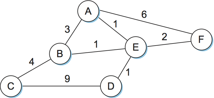
Figure 84. Network represented as a graph.
The basic problem of routing is to find the lowest-cost path between any two nodes, where the cost of a path equals the sum of the costs of all the edges that make up the path. For a simple network like the one in Figure 84, you could imagine just calculating all the shortest paths and loading them into some nonvolatile storage on each node. Such a static approach has several shortcomings:
It does not deal with node or link failures.
It does not consider the addition of new nodes or links.
It implies that edge costs cannot change, even though we might reasonably wish to have link costs change over time (e.g., assigning high cost to a link that is heavily loaded).
For these reasons, routing is achieved in most practical networks by running routing protocols among the nodes. These protocols provide a distributed, dynamic way to solve the problem of finding the lowest-cost path in the presence of link and node failures and changing edge costs. Note the word distributed in the previous sentence; it is difficult to make centralized solutions scalable, so all the widely used routing protocols use distributed algorithms.
The distributed nature of routing algorithms is one of the main reasons why this has been such a rich field of research and development—there are a lot of challenges in making distributed algorithms work well. For example, distributed algorithms raise the possibility that two routers will at one instant have different ideas about the shortest path to some destination. In fact, each one may think that the other one is closer to the destination and decide to send packets to the other one. Clearly, such packets will be stuck in a loop until the discrepancy between the two routers is resolved, and it would be good to resolve it as soon as possible. This is just one example of the type of problem routing protocols must address.
To begin our analysis, we assume that the edge costs in the network are known. We will examine the two main classes of routing protocols: distance vector and link state. In a later section, we return to the problem of calculating edge costs in a meaningful way.
3.4 2 Distance-Vector (RIP)
The idea behind the distance-vector algorithm is suggested by its name. (The other common name for this class of algorithm is Bellman-Ford, after its inventors.) Each node constructs a one-dimensional array (a vector) containing the “distances” (costs) to all other nodes and distributes that vector to its immediate neighbors. The starting assumption for distance-vector routing is that each node knows the cost of the link to each of its directly connected neighbors. These costs may be provided when the router is configured by a network manager. A link that is down is assigned an infinite cost.
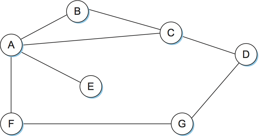
Figure 85. Distance-vector routing: an example network.
A |
B |
C |
D |
E |
F |
G |
|
|---|---|---|---|---|---|---|---|
A |
0 |
1 |
1 |
∞ |
1 |
1 |
∞ |
B |
1 |
0 |
1 |
∞ |
∞ |
∞ |
∞ |
C |
1 |
1 |
0 |
1 |
∞ |
∞ |
∞ |
D |
∞ |
∞ |
1 |
0 |
∞ |
∞ |
1 |
E |
1 |
∞ |
∞ |
∞ |
0 |
∞ |
∞ |
F |
1 |
∞ |
∞ |
∞ |
∞ |
0 |
1 |
G |
∞ |
∞ |
∞ |
1 |
∞ |
1 |
0 |
To see how a distance-vector routing algorithm works, it is easiest to consider an example like the one depicted in Figure 85. In this example, the cost of each link is set to 1, so that a least-cost path is simply the one with the fewest hops. (Since all edges have the same cost, we do not show the costs in the graph.) We can represent each node’s knowledge about the distances to all other nodes as a table like Table 16. Note that each node knows only the information in one row of the table (the one that bears its name in the left column). The global view that is presented here is not available at any single point in the network.
We may consider each row in Table 16 as a list of distances from one node to all other nodes, representing the current beliefs of that node. Initially, each node sets a cost of 1 to its directly connected neighbors and ∞ to all other nodes. Thus, A initially believes that it can reach B in one hop and that D is unreachable. The routing table stored at A reflects this set of beliefs and includes the name of the next hop that A would use to reach any reachable node. Initially, then, A’s routing table would look like Table 17.
Destination |
Cost |
NextHop |
|---|---|---|
B |
1 |
B |
C |
1 |
C |
D |
∞ |
— |
E |
1 |
E |
F |
1 |
F |
G |
∞ |
— |
The next step in distance-vector routing is that every node sends a message to its directly connected neighbors containing its personal list of distances. For example, node F tells node A that it can reach node G at a cost of 1; A also knows it can reach F at a cost of 1, so it adds these costs to get the cost of reaching G by means of F. This total cost of 2 is less than the current cost of infinity, so A records that it can reach G at a cost of 2 by going through F. Similarly, A learns from C that D can be reached from C at a cost of 1; it adds this to the cost of reaching C (1) and decides that D can be reached via C at a cost of 2, which is better than the old cost of infinity. At the same time, A learns from C that B can be reached from C at a cost of 1, so it concludes that the cost of reaching B via C is 2. Since this is worse than the current cost of reaching B (1), this new information is ignored. At this point, A can update its routing table with costs and next hops for all nodes in the network. The result is shown in Table 18.
Destination |
Cost |
NextHop |
|---|---|---|
B |
1 |
B |
C |
1 |
C |
D |
2 |
C |
E |
1 |
E |
F |
1 |
F |
G |
2 |
F |
In the absence of any topology changes, it takes only a few exchanges of information between neighbors before each node has a complete routing table. The process of getting consistent routing information to all the nodes is called convergence. Table 19 shows the final set of costs from each node to all other nodes when routing has converged. We must stress that there is no one node in the network that has all the information in this table—each node only knows about the contents of its own routing table. The beauty of a distributed algorithm like this is that it enables all nodes to achieve a consistent view of the network in the absence of any centralized authority.
A |
B |
C |
D |
E |
F |
G |
|
|---|---|---|---|---|---|---|---|
A |
0 |
1 |
1 |
2 |
1 |
1 |
2 |
B |
1 |
0 |
1 |
2 |
2 |
2 |
3 |
C |
1 |
1 |
0 |
1 |
2 |
2 |
2 |
D |
2 |
2 |
1 |
0 |
3 |
2 |
1 |
E |
1 |
2 |
2 |
3 |
0 |
2 |
3 |
F |
1 |
2 |
2 |
2 |
2 |
0 |
1 |
G |
2 |
3 |
2 |
1 |
3 |
1 |
0 |
There are a few details to fill in before our discussion of distance-vector routing is complete. First we note that there are two different circumstances under which a given node decides to send a routing update to its neighbors. One of these circumstances is the periodic update. In this case, each node automatically sends an update message every so often, even if nothing has changed. This serves to let the other nodes know that this node is still running. It also makes sure that they keep getting information that they may need if their current routes become unviable. The frequency of these periodic updates varies from protocol to protocol, but it is typically on the order of several seconds to several minutes. The second mechanism, sometimes called a triggered update, happens whenever a node notices a link failure or receives an update from one of its neighbors that causes it to change one of the routes in its routing table. Whenever a node’s routing table changes, it sends an update to its neighbors, which may lead to a change in their tables, causing them to send an update to their neighbors.
Now consider what happens when a link or node fails. The nodes that notice first send new lists of distances to their neighbors, and normally the system settles down fairly quickly to a new state. As to the question of how a node detects a failure, there are a couple of different answers. In one approach, a node continually tests the link to another node by sending a control packet and seeing if it receives an acknowledgment. In another approach, a node determines that the link (or the node at the other end of the link) is down if it does not receive the expected periodic routing update for the last few update cycles.
To understand what happens when a node detects a link failure, consider what happens when F detects that its link to G has failed. First, F sets its new distance to G to infinity and passes that information along to A. Since A knows that its 2-hop path to G is through F, A would also set its distance to G to infinity. However, with the next update from C, A would learn that C has a 2-hop path to G. Thus, A would know that it could reach G in 3 hops through C, which is less than infinity, and so A would update its table accordingly. When it advertises this to F, node F would learn that it can reach G at a cost of 4 through A, which is less than infinity, and the system would again become stable.
Unfortunately, slightly different circumstances can prevent the network from stabilizing. Suppose, for example, that the link from A to E goes down. In the next round of updates, A advertises a distance of infinity to E, but B and C advertise a distance of 2 to E. Depending on the exact timing of events, the following might happen: Node B, upon hearing that E can be reached in 2 hops from C, concludes that it can reach E in 3 hops and advertises this to A; node A concludes that it can reach E in 4 hops and advertises this to C; node C concludes that it can reach E in 5 hops; and so on. This cycle stops only when the distances reach some number that is large enough to be considered infinite. In the meantime, none of the nodes actually knows that E is unreachable, and the routing tables for the network do not stabilize. This situation is known as the count to infinity problem.
There are several partial solutions to this problem. The first one is to use some relatively small number as an approximation of infinity. For example, we might decide that the maximum number of hops to get across a certain network is never going to be more than 16, and so we could pick 16 as the value that represents infinity. This at least bounds the amount of time that it takes to count to infinity. Of course, it could also present a problem if our network grew to a point where some nodes were separated by more than 16 hops.
One technique to improve the time to stabilize routing is called split horizon. The idea is that when a node sends a routing update to its neighbors, it does not send those routes it learned from each neighbor back to that neighbor. For example, if B has the route (E, 2, A) in its table, then it knows it must have learned this route from A, and so whenever B sends a routing update to A, it does not include the route (E, 2) in that update. In a stronger variation of split horizon, called split horizon with poison reverse, B actually sends that route back to A, but it puts negative information in the route to ensure that A will not eventually use B to get to E. For example, B sends the route (E, ∞) to A. The problem with both of these techniques is that they only work for routing loops that involve two nodes. For larger routing loops, more drastic measures are called for. Continuing the above example, if B and C had waited for a while after hearing of the link failure from A before advertising routes to E, they would have found that neither of them really had a route to E. Unfortunately, this approach delays the convergence of the protocol; speed of convergence is one of the key advantages of its competitor, link-state routing, the subject of a later section.
Implementation
The code that implements this algorithm is very straightforward; we give
only some of the basics here. Structure Route defines each entry in
the routing table, and constant MAX_TTL specifies how long an entry
is kept in the table before it is discarded.
#define MAX_ROUTES      128     /* maximum size of routing table */
#define MAX_TTL         120     /* time (in seconds) until route expires */

typedef struct {
    NodeAddr  Destination;    /* address of destination */
    NodeAddr  NextHop;        /* address of next hop */
    int        Cost;          /* distance metric */
    u_short   TTL;            /* time to live */
} Route;

int      numRoutes = 0;
Route    routingTable[MAX_ROUTES];
The routine that updates the local node’s routing table based on a new
route is given by mergeRoute. Although not shown, a timer function
periodically scans the list of routes in the node’s routing table,
decrements the TTL (time to live) field of each route, and discards
any routes that have a time to live of 0. Notice, however, that the
TTL field is reset to MAX_TTL any time the route is reconfirmed
by an update message from a neighboring node.
void
mergeRoute (Route *new)
{
    int i;

    for (i = 0; i < numRoutes; ++i)
    {
        if (new->Destination == routingTable[i].Destination)
        {
            if (new->Cost + 1 < routingTable[i].Cost)
            {
                /* found a better route: */
                break;
            } else if (new->NextHop == routingTable[i].NextHop) {
                /* metric for current next-hop may have changed: */
                break;
            } else {
                /* route is uninteresting---just ignore it */
                return;
            }
        }
    }
    if (i == numRoutes)
    {
        /* this is a completely new route; is there room for it? */
        if (numRoutes < MAXROUTES)
        {
            ++numRoutes;
        } else {
            /* can`t fit this route in table so give up */
            return;
        }
    }
    routingTable[i] = *new;
    /* reset TTL */
    routingTable[i].TTL = MAX_TTL;
    /* account for hop to get to next node */
    ++routingTable[i].Cost;
}
Finally, the procedure updateRoutingTable is the main routine that
calls mergeRoute to incorporate all the routes contained in a
routing update that is received from a neighboring node.
void
updateRoutingTable (Route *newRoute, int numNewRoutes)
{
    int i;

    for (i=0; i < numNewRoutes; ++i)
    {
        mergeRoute(&newRoute[i]);
    }
}
Routing Information Protocol (RIP)
One of the more widely used routing protocols in IP networks is the Routing Information Protocol (RIP). Its widespread use in the early days of IP was due in no small part to the fact that it was distributed along with the popular Berkeley Software Distribution (BSD) version of Unix, from which many commercial versions of Unix were derived. It is also extremely simple. RIP is the canonical example of a routing protocol built on the distance-vector algorithm just described.
Routing protocols in internetworks differ very slightly from the idealized graph model described above. In an internetwork, the goal of the routers is to learn how to forward packets to various networks. Thus, rather than advertising the cost of reaching other routers, the routers advertise the cost of reaching networks. For example, in Figure 86, router C would advertise to router A the fact that it can reach networks 2 and 3 (to which it is directly connected) at a cost of 0, networks 5 and 6 at cost 1, and network 4 at cost 2.
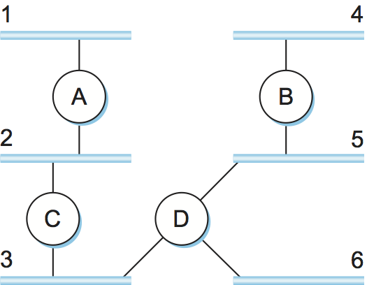
Figure 86. Example network running RIP.
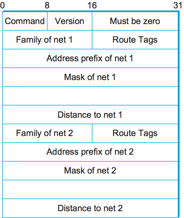
Figure 87. RIPv2 packet format.
We can see evidence of this in the RIP (version 2) packet format in
Figure 87. The majority of the packet is taken up
with (address, mask, distance) triples. However, the principles of
the routing algorithm are just the same. For example, if router A
learns from router B that network X can be reached at a lower cost via
B than via the existing next hop in the routing table, A updates the
cost and next hop information for the network number accordingly.
RIP is in fact a fairly straightforward implementation of
distance-vector routing. Routers running RIP send their advertisements
every 30 seconds; a router also sends an update message whenever an
update from another router causes it to change its routing table. One
point of interest is that it supports multiple address families, not
just IP—that is the reason for the Family part of the
advertisements. RIP version 2 (RIPv2) also introduced the subnet masks
described in an earlier section, whereas RIP version 1 worked with the
old classful addresses of IP.
As we will see below, it is possible to use a range of different metrics or costs for the links in a routing protocol. RIP takes the simplest approach, with all link costs being equal to 1, just as in our example above. Thus, it always tries to find the minimum hop route. Valid distances are 1 through 15, with 16 representing infinity. This also limits RIP to running on fairly small networks—those with no paths longer than 15 hops.
3.4.3 Link State (OSPF)
Link-state routing is the second major class of intradomain routing protocol. The starting assumptions for link-state routing are rather similar to those for distance-vector routing. Each node is assumed to be capable of finding out the state of the link to its neighbors (up or down) and the cost of each link. Again, we want to provide each node with enough information to enable it to find the least-cost path to any destination. The basic idea behind link-state protocols is very simple: Every node knows how to reach its directly connected neighbors, and if we make sure that the totality of this knowledge is disseminated to every node, then every node will have enough knowledge of the network to build a complete map of the network. This is clearly a sufficient condition (although not a necessary one) for finding the shortest path to any point in the network. Thus, link-state routing protocols rely on two mechanisms: reliable dissemination of link-state information, and the calculation of routes from the sum of all the accumulated link-state knowledge.
Reliable Flooding
Reliable flooding is the process of making sure that all the nodes participating in the routing protocol get a copy of the link-state information from all the other nodes. As the term flooding suggests, the basic idea is for a node to send its link-state information out on all of its directly connected links; each node that receives this information then forwards it out on all of its links. This process continues until the information has reached all the nodes in the network.
More precisely, each node creates an update packet, also called a link-state packet (LSP), which contains the following information:
The ID of the node that created the LSP
A list of directly connected neighbors of that node, with the cost of the link to each one
A sequence number
A time to live for this packet
The first two items are needed to enable route calculation; the last two are used to make the process of flooding the packet to all nodes reliable. Reliability includes making sure that you have the most recent copy of the information, since there may be multiple, contradictory LSPs from one node traversing the network. Making the flooding reliable has proven to be quite difficult. (For example, an early version of link-state routing used in the ARPANET caused that network to fail in 1981.)
Flooding works in the following way. First, the transmission of LSPs between adjacent routers is made reliable using acknowledgments and retransmissions just as in the reliable link-layer protocol. However, several more steps are necessary to reliably flood an LSP to all nodes in a network.
Consider a node X that receives a copy of an LSP that originated at some other node Y. Note that Y may be any other router in the same routing domain as X. X checks to see if it has already stored a copy of an LSP from Y. If not, it stores the LSP. If it already has a copy, it compares the sequence numbers; if the new LSP has a larger sequence number, it is assumed to be the more recent, and that LSP is stored, replacing the old one. A smaller (or equal) sequence number would imply an LSP older (or not newer) than the one stored, so it would be discarded and no further action would be needed. If the received LSP was the newer one, X then sends a copy of that LSP to all of its neighbors except the neighbor from which the LSP was just received. The fact that the LSP is not sent back to the node from which it was received helps to bring an end to the flooding of an LSP. Since X passes the LSP on to all its neighbors, who then turn around and do the same thing, the most recent copy of the LSP eventually reaches all nodes.
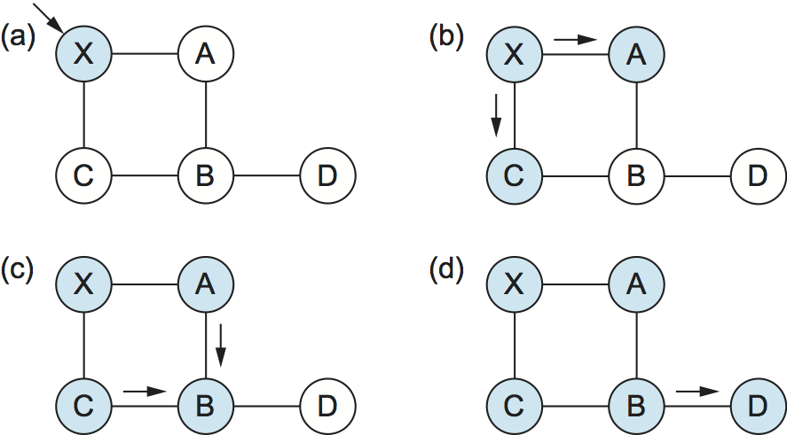
Figure 88. Flooding of link-state packets: (a) LSP arrives at node X; (b) X floods LSP to A and C; (c) A and C flood LSP to B (but not X); (d) flooding is complete.
Figure 88 shows an LSP being flooded in a small network. Each node becomes shaded as it stores the new LSP. In Figure 88(a) the LSP arrives at node X, which sends it to neighbors A and C in Figure 88(b). A and C do not send it back to X, but send it on to B. Since B receives two identical copies of the LSP, it will accept whichever arrived first and ignore the second as a duplicate. It then passes the LSP onto D, which has no neighbors to flood it to, and the process is complete.
Just as in RIP, each node generates LSPs under two circumstances. Either the expiry of a periodic timer or a change in topology can cause a node to generate a new LSP. However, the only topology-based reason for a node to generate an LSP is if one of its directly connected links or immediate neighbors has gone down. The failure of a link can be detected in some cases by the link-layer protocol. The demise of a neighbor or loss of connectivity to that neighbor can be detected using periodic “hello” packets. Each node sends these to its immediate neighbors at defined intervals. If a sufficiently long time passes without receipt of a “hello” from a neighbor, the link to that neighbor will be declared down, and a new LSP will be generated to reflect this fact.
One of the important design goals of a link-state protocol’s flooding mechanism is that the newest information must be flooded to all nodes as quickly as possible, while old information must be removed from the network and not allowed to circulate. In addition, it is clearly desirable to minimize the total amount of routing traffic that is sent around the network; after all, this is just overhead from the perspective of those who actually use the network for their applications. The next few paragraphs describe some of the ways that these goals are accomplished.
One easy way to reduce overhead is to avoid generating LSPs unless absolutely necessary. This can be done by using very long timers—often on the order of hours—for the periodic generation of LSPs. Given that the flooding protocol is truly reliable when topology changes, it is safe to assume that messages saying “nothing has changed” do not need to be sent very often.
To make sure that old information is replaced by newer information, LSPs carry sequence numbers. Each time a node generates a new LSP, it increments the sequence number by 1. Unlike most sequence numbers used in protocols, these sequence numbers are not expected to wrap, so the field needs to be quite large (say, 64 bits). If a node goes down and then comes back up, it starts with a sequence number of 0. If the node was down for a long time, all the old LSPs for that node will have timed out (as described below); otherwise, this node will eventually receive a copy of its own LSP with a higher sequence number, which it can then increment and use as its own sequence number. This will ensure that its new LSP replaces any of its old LSPs left over from before the node went down.
LSPs also carry a time to live. This is used to ensure that old link-state information is eventually removed from the network. A node always decrements the TTL of a newly received LSP before flooding it to its neighbors. It also “ages” the LSP over time while it is stored in the node. When the TTL reaches 0, the node refloods the LSP (with the TTL of 0), which is interpreted by all the nodes in the network as a signal to delete that LSP.
Route Calculation
Once a given node has a copy of the LSP from every other node, it is able to compute a complete map for the topology of the network, and from this map it is able to decide the best route to each destination. The question, then, is exactly how it calculates routes from this information. The solution is based on a well-known algorithm from graph theory—Dijkstra’s shortest-path algorithm.
We first define Dijkstra’s algorithm in graph-theoretic terms. Imagine that a node takes all the LSPs it has received and constructs a graphical representation of the network, in which N denotes the set of nodes in the graph, l(i,j) denotes the nonnegative cost (weight) associated with the edge between nodes i, j in N and l(i, j) = ∞ if no edge connects i and j. In the following description, we let s in N denote this node, that is, the node executing the algorithm to find the shortest path to all the other nodes in N. Also, the algorithm maintains the following two variables: M denotes the set of nodes incorporated so far by the algorithm, and C(n) denotes the cost of the path from s to each node n. Given these definitions, the algorithm is defined as follows:
M = {s}
for each n in N - {s}
    C(n) = l(s,n)
while (N != M)
    M = M + {w} such that C(w) is the minimum for all w in (N-M)
    for each n in (N-M)
    C(n) = MIN(C(n), C(w)+l(w,n))
Basically, the algorithm works as follows. We start with M containing
this node s and then initialize the table of costs (the array C(n))
to other nodes using the known costs to directly connected nodes. We
then look for the node that is reachable at the lowest cost (w) and add
it to M. Finally, we update the table of costs by considering the cost
of reaching nodes through w. In the last line of the algorithm, we
choose a new route to node n that goes through node w if the total cost
of going from the source to w and then following the link from w to n is
less than the old route we had to n. This procedure is repeated until
all nodes are incorporated in M.
In practice, each switch computes its routing table directly from the
LSPs it has collected using a realization of Dijkstra’s algorithm called
the forward search algorithm. Specifically, each switch maintains two
lists, known as Tentative and Confirmed. Each of these lists
contains a set of entries of the form (Destination, Cost, NextHop).
The algorithm works as follows:
Initialize the
Confirmedlist with an entry for myself; this entry has a cost of 0.For the node just added to the
Confirmedlist in the previous step, call it nodeNextand select its LSP.For each neighbor (
Neighbor) ofNext, calculate the cost (Cost) to reach thisNeighboras the sum of the cost from myself toNextand fromNexttoNeighbor.If
Neighboris currently on neither theConfirmednor theTentativelist, then add(Neighbor, Cost, NextHop)to theTentativelist, whereNextHopis the direction I go to reachNext.If
Neighboris currently on theTentativelist, and theCostis less than the currently listed cost forNeighbor, then replace the current entry with(Neighbor, Cost, NextHop), whereNextHopis the direction I go to reachNext.
If the
Tentativelist is empty, stop. Otherwise, pick the entry from theTentativelist with the lowest cost, move it to theConfirmedlist, and return to step 2.
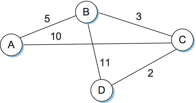
Figure 89. Link-state routing: an example network.
This will become a lot easier to understand when we look at an
example. Consider the network depicted in Figure 89. Note that, unlike our previous example, this network
has a range of different edge costs. Table 20
traces the steps for building the routing table for node D. We denote
the two outputs of D by using the names of the nodes to which they
connect, B and C. Note the way the algorithm seems to head off on
false leads (like the 11-unit cost path to B that was the first
addition to the Tentative list) but ends up with the least-cost
paths to all nodes.
Step |
Confirmed |
Tentative |
Comments |
|---|---|---|---|
1 |
(D,0,–) |
Since D is the only new member of the confirmed list, look at its LSP. |
|
2 |
(D,0,–) |
(B,11,B) (C,2,C) |
D’s LSP says we
can reach B
through B at cost
11, which is
better than
anything else on
either list, so
put it on
|
3 |
(D,0,–) (C,2,C) |
(B,11,B) |
Put lowest-cost
member of
|
4 |
(D,0,–) (C,2,C) |
(B,5,C) (A,12,C) |
Cost to reach B through C is 5, so replace (B,11,B). C’s LSP tells us that we can reach A at cost 12. |
5 |
(D,0,–) (C,2,C) (B,5,C) |
(A,12,C) |
Move lowest-cost
member of
|
6 |
(D,0,–) (C,2,C) (B,5,C) |
(A,10,C) |
Since we can
reach A at cost 5
through B,
replace the
|
7 |
(D,0,–) (C,2,C) (B,5,C) (A,10,C) |
Move lowest-cost
member of
|
The link-state routing algorithm has many nice properties: It has been proven to stabilize quickly, it does not generate much traffic, and it responds rapidly to topology changes or node failures. On the downside, the amount of information stored at each node (one LSP for every other node in the network) can be quite large. This is one of the fundamental problems of routing and is an instance of the more general problem of scalability. Some solutions to both the specific problem (the amount of storage potentially required at each node) and the general problem (scalability) will be discussed in the next section.
Key Takeaway
Distance-vector and link-state are both distributed routing algorithms, but they adopt different strategies. In distance-vector, each node talks only to its directly connected neighbors, but it tells them everything it has learned (i.e., distance to all nodes). In link-state, each node talks to all other nodes, but it tells them only what it knows for sure (i.e., only the state of its directly connected links). In contrast to both of these algorithms, we will consider a more centralized approach to routing in Section 3.5 when we introduce Software Defined Networking (SDN). [Next]
The Open Shortest Path First Protocol (OSPF)
One of the most widely used link-state routing protocols is OSPF. The first word, “Open,” refers to the fact that it is an open, nonproprietary standard, created under the auspices of the Internet Engineering Task Force (IETF). The “SPF” part comes from an alternative name for link-state routing. OSPF adds quite a number of features to the basic link-state algorithm described above, including the following:
Authentication of routing messages—One feature of distributed routing algorithms is that they disperse information from one node to many other nodes, and the entire network can thus be impacted by bad information from one node. For this reason, it’s a good idea to be sure that all the nodes taking part in the protocol can be trusted. Authenticating routing messages helps achieve this. Early versions of OSPF used a simple 8-byte password for authentication. This is not a strong enough form of authentication to prevent dedicated malicious users, but it alleviates some problems caused by misconfiguration or casual attacks. (A similar form of authentication was added to RIP in version 2.) Strong cryptographic authentication was later added.
Additional hierarchy—Hierarchy is one of the fundamental tools used to make systems more scalable. OSPF introduces another layer of hierarchy into routing by allowing a domain to be partitioned into areas. This means that a router within a domain does not necessarily need to know how to reach every network within that domain—it may be able to get by knowing only how to get to the right area. Thus, there is a reduction in the amount of information that must be transmitted to and stored in each node.
Load balancing—OSPF allows multiple routes to the same place to be assigned the same cost and will cause traffic to be distributed evenly over those routes, thus making better use of the available network capacity.
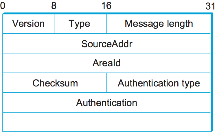
Figure 90. OSPF header format.
There are several different types of OSPF messages, but all begin with
the same header, as shown in Figure 90. The
Version field is currently set to 2, and the Type field may
take the values 1 through 5. The SourceAddr identifies the sender
of the message, and the AreaId is a 32-bit identifier of the area
in which the node is located. The entire packet, except the
authentication data, is protected by a 16-bit checksum using the same
algorithm as the IP header. The Authentication type is 0 if no
authentication is used; otherwise, it may be 1, implying that a simple
password is used, or 2, which indicates that a cryptographic
authentication checksum is used. In the latter cases, the
Authentication field carries the password or cryptographic
checksum.
Of the five OSPF message types, type 1 is the “hello” message, which a router sends to its peers to notify them that it is still alive and connected as described above. The remaining types are used to request, send, and acknowledge the receipt of link-state messages. The basic building block of link-state messages in OSPF is the link-state advertisement (LSA). One message may contain many LSAs. We provide a few details of the LSA here.
Like any internetwork routing protocol, OSPF must provide information about how to reach networks. Thus, OSPF must provide a little more information than the simple graph-based protocol described above. Specifically, a router running OSPF may generate link-state packets that advertise one or more of the networks that are directly connected to that router. In addition, a router that is connected to another router by some link must advertise the cost of reaching that router over the link. These two types of advertisements are necessary to enable all the routers in a domain to determine the cost of reaching all networks in that domain and the appropriate next hop for each network.
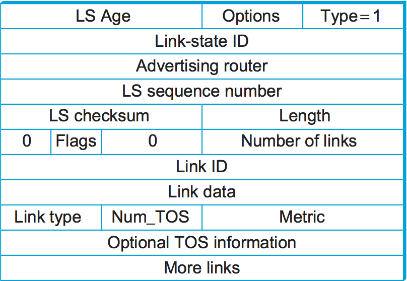
Figure 91. OSPF link-state advertisement.
Figure 91 shows the packet format for a
type 1 link-state advertisement. Type 1 LSAs advertise the cost of
links between routers. Type 2 LSAs are used to advertise networks to
which the advertising router is connected, while other types are used
to support additional hierarchy as described in the next section. Many
fields in the LSA should be familiar from the preceding
discussion. The LS Age is the equivalent of a time to live, except
that it counts up and the LSA expires when the age reaches a defined
maximum value. The Type field tells us that this is a type 1 LSA.
In a type 1 LSA, the Link state ID and the Advertising router
field are identical. Each carries a 32-bit identifier for the router
that created this LSA. While a number of assignment strategies may be
used to assign this ID, it is essential that it be unique in the routing
domain and that a given router consistently uses the same router ID. One
way to pick a router ID that meets these requirements would be to pick
the lowest IP address among all the IP addresses assigned to that
router. (Recall that a router may have a different IP address on each of
its interfaces.)
The LS sequence number is used exactly as described above to detect
old or duplicate LSAs. The LS checksum is similar to others we have
seen in other protocols; it is, of course, used to verify that data has
not been corrupted. It covers all fields in the packet except
LS Age, so it is not necessary to recompute a checksum every time
LS Age is incremented. Length is the length in bytes of the
complete LSA.
Now we get to the actual link-state information. This is made a little
complicated by the presence of TOS (type of service) information.
Ignoring that for a moment, each link in the LSA is represented by a
Link ID, some Link Data, and a metric. The first two of
these fields identify the link; a common way to do this would be to use
the router ID of the router at the far end of the link as the
Link ID and then use the Link Data to disambiguate among
multiple parallel links if necessary. The metric is of course the
cost of the link. Type tells us something about the link—for
example, if it is a point-to-point link.
The TOS information is present to allow OSPF to choose different routes for IP packets based on the value in their TOS field. Instead of assigning a single metric to a link, it is possible to assign different metrics depending on the TOS value of the data. For example, if we had a link in our network that was very good for delay-sensitive traffic, we could give it a low metric for the TOS value representing low delay and a high metric for everything else. OSPF would then pick a different shortest path for those packets that had their TOS field set to that value. It is worth noting that, at the time of writing, this capability has not been widely deployed.
3.4.4 Metrics
The preceding discussion assumes that link costs, or metrics, are known when we execute the routing algorithm. In this section, we look at some ways to calculate link costs that have proven effective in practice. One example that we have seen already, which is quite reasonable and very simple, is to assign a cost of 1 to all links—the least-cost route will then be the one with the fewest hops. Such an approach has several drawbacks, however. First, it does not distinguish between links on a latency basis. Thus, a satellite link with 250-ms latency looks just as attractive to the routing protocol as a terrestrial link with 1-ms latency. Second, it does not distinguish between routes on a capacity basis, making a 1-Mbps link look just as good as a 10-Gbps link. Finally, it does not distinguish between links based on their current load, making it impossible to route around overloaded links. It turns out that this last problem is the hardest because you are trying to capture the complex and dynamic characteristics of a link in a single scalar cost.
The ARPANET was the testing ground for a number of different approaches to link-cost calculation. (It was also the place where the superior stability of link-state over distance-vector routing was demonstrated; the original mechanism used distance vector while the later version used link state.) The following discussion traces the evolution of the ARPANET routing metric and, in so doing, explores the subtle aspects of the problem.
The original ARPANET routing metric measured the number of packets that were queued waiting to be transmitted on each link, meaning that a link with 10 packets queued waiting to be transmitted was assigned a larger cost weight than a link with 5 packets queued for transmission. Using queue length as a routing metric did not work well, however, since queue length is an artificial measure of load—it moves packets toward the shortest queue rather than toward the destination, a situation all too familiar to those of us who hop from line to line at the grocery store. Stated more precisely, the original ARPANET routing mechanism suffered from the fact that it did not take either the bandwidth or the latency of the link into consideration.
A second version of the ARPANET routing algorithm took both link
bandwidth and latency into consideration and used delay, rather than
just queue length, as a measure of load. This was done as follows.
First, each incoming packet was timestamped with its time of arrival at
the router (ArrivalTime); its departure time from the router
(DepartTime) was also recorded. Second, when the link-level ACK was
received from the other side, the node computed the delay for that
packet as
Delay = (DepartTime - ArrivalTime) + TransmissionTime + Latency
where TransmissionTime and Latency were statically defined for
the link and captured the link’s bandwidth and latency, respectively.
Notice that in this case, DepartTime - ArrivalTime represents the
amount of time the packet was delayed (queued) in the node due to load.
If the ACK did not arrive, but instead the packet timed out, then
DepartTime was reset to the time the packet was retransmitted. In
this case, DepartTime - ArrivalTime captures the reliability of the
link—the more frequent the retransmission of packets, the less reliable
the link, and the more we want to avoid it. Finally, the weight assigned
to each link was derived from the average delay experienced by the
packets recently sent over that link.
Although an improvement over the original mechanism, this approach also had a lot of problems. Under light load, it worked reasonably well, since the two static factors of delay dominated the cost. Under heavy load, however, a congested link would start to advertise a very high cost. This caused all the traffic to move off that link, leaving it idle, so then it would advertise a low cost, thereby attracting back all the traffic, and so on. The effect of this instability was that, under heavy load, many links would in fact spend a great deal of time being idle, which is the last thing you want under heavy load.
Another problem was that the range of link values was much too large. For example, a heavily loaded 9.6-kbps link could look 127 times more costly than a lightly loaded 56-kbps link. (Keep in mind, we’re talking about the ARPANET circa 1975.) This means that the routing algorithm would choose a path with 126 hops of lightly loaded 56-kbps links in preference to a 1-hop 9.6-kbps path. While shedding some traffic from an overloaded line is a good idea, making it look so unattractive that it loses all its traffic is excessive. Using 126 hops when 1 hop will do is in general a bad use of network resources. Also, satellite links were unduly penalized, so that an idle 56-kbps satellite link looked considerably more costly than an idle 9.6-kbps terrestrial link, even though the former would give better performance for high-bandwidth applications.
A third approach addressed these problems. The major changes were to compress the dynamic range of the metric considerably, to account for the link type, and to smooth the variation of the metric with time.
The smoothing was achieved by several mechanisms. First, the delay measurement was transformed to a link utilization, and this number was averaged with the last reported utilization to suppress sudden changes. Second, there was a hard limit on how much the metric could change from one measurement cycle to the next. By smoothing the changes in the cost, the likelihood that all nodes would abandon a route at once is greatly reduced.
The compression of the dynamic range was achieved by feeding the measured utilization, the link type, and the link speed into a function that is shown graphically in Figure 92. below. Observe the following:
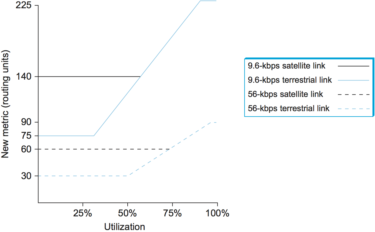
Figure 92. Revised ARPANET routing metric versus link utilization.
A highly loaded link never shows a cost of more than three times its cost when idle.
The most expensive link is only seven times the cost of the least expensive.
A high-speed satellite link is more attractive than a low-speed terrestrial link.
Cost is a function of link utilization only at moderate to high loads.
All of these factors mean that a link is much less likely to be universally abandoned, since a threefold increase in cost is likely to make the link unattractive for some paths while letting it remain the best choice for others. The slopes, offsets, and breakpoints for the curves in Figure 92 were arrived at by a great deal of trial and error, and they were carefully tuned to provide good performance.
Despite all these improvements, it turns out that in the majority of real-world network deployments, metrics change rarely if at all and only under the control of a network administrator, not automatically as described above. The reason for this is partly that conventional wisdom now holds that dynamically changing metrics are too unstable, even though this probably need not be true. Perhaps more significantly, many networks today lack the great disparity of link speeds and latencies that prevailed in the ARPANET. Thus, static metrics are the norm. One common approach to setting metrics is to use a constant multiplied by (1/link_bandwidth).
Key Takeaway
Why do we still tell the story about a decades old algorithm that’s no longer in use? Because it perfectly illustrates two valuable lessons. The first is that computer systems are often designed iteratively based on experience. We seldom get it right the first time, so it’s important to deploy a simple solution sooner rather than later, and expect to improve it over time. Staying stuck in the design phase indefinitely is usually not a good plan. The second is the well-know KISS principle: Keep it Simple, Stupid. When building a complex system, less is often more. Opportunities to invent sophisticated optimizations are plentiful, and it’s a tempting opportunity to pursue. While such optimizations sometimes have short-term value, it is shocking how often a simple approach proves best over time. This is because when a system has many moving parts, as the Internet most certainly does, keeping each part as simple as possible is usually the best approach. [Next]