2.6 Multi-Access Networks
Developed in the mid-1970s by researchers at the Xerox Palo Alto Research Center (PARC), the Ethernet eventually became the dominant local area networking technology, emerging from a pack of competing technologies. Today, it competes mainly with 802.11 wireless networks but remains extremely popular in campus networks and data centers. The more general name for the technology behind the Ethernet is Carrier Sense, Multiple Access with Collision Detect (CSMA/CD).
As indicated by the CSMA name, the Ethernet is a multiple-access network, meaning that a set of nodes sends and receives frames over a shared link. You can, therefore, think of an Ethernet as being like a bus that has multiple stations plugged into it. The “carrier sense” in CSMA/CD means that all the nodes can distinguish between an idle and a busy link, and “collision detect” means that a node listens as it transmits and can therefore detect when a frame it is transmitting has interfered (collided) with a frame transmitted by another node.
The Ethernet has its roots in an early packet radio network, called Aloha, developed at the University of Hawaii to support computer communication across the Hawaiian Islands. Like the Aloha network, the fundamental problem faced by the Ethernet is how to mediate access to a shared medium fairly and efficiently (in Aloha, the medium was the atmosphere, while in the Ethernet the medium was originally a coax cable). The core idea in both Aloha and the Ethernet is an algorithm that controls when each node can transmit.
Modern Ethernet links are now largely point to point; that is, they connect one host to an Ethernet switch, or they interconnect switches. As a consequence, the “multiple access” algorithm is not used much in today’s wired Ethernets, but a variant is now used in wireless networks, such as 802.11 networks (also known as Wi-Fi). Due to the enormous influence of Ethernet, we chose to describe its classic algorithm here, and then explain how it has been adapted to Wi-Fi in the next section. We will also discuss Ethernet switches elsewhere. For now, we’ll focus on how a single Ethernet link works.
Digital Equipment Corporation and Intel Corporation joined Xerox to define a 10-Mbps Ethernet standard in 1978. This standard then formed the basis for IEEE standard 802.3, which additionally defines a much wider collection of physical media over which an Ethernet can operate, including 100-Mbps, 1-Gbps, 10-Gbps, 40-Gbps, and 100-Gbps versions.
2.6.1 Physical Properties
Ethernet segments were originally implemented using coaxial cable of length up to 500 m. (Modern Ethernets use twisted copper pairs, usually a particular type known as “Category 5,” or optical fibers, and in some cases can be quite a lot longer than 500 m.) This cable was similar to the type used for cable TV. Hosts connected to an Ethernet segment by tapping into it. A transceiver, a small device directly attached to the tap, detected when the line was idle and drove the signal when the host was transmitting. It also received incoming signals. The transceiver, in turn, connected to an Ethernet adaptor, which was plugged into the host. This configuration is shown in Figure 39.
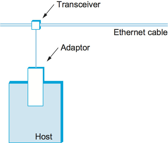
Figure 39. Ethernet transceiver and adaptor.
Multiple Ethernet segments can be joined together by repeaters (or a multi-port variant of a repeater, called a hub). A repeater is a device that forwards digital signals, much like an amplifier forwards analog signals; repeaters do not understand bits or frames. No more than four repeaters could be positioned between any pair of hosts, meaning that a classical Ethernet had a total reach of only 2500 m. For example, using just two repeaters between any pair of hosts supports a configuration similar to the one illustrated in Figure 40; that is, a segment running down the spine of a building with a segment on each floor.
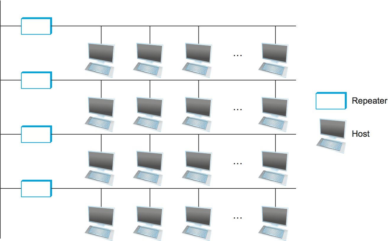
Figure 40. Ethernet repeater, interconnecting segments to form a larger collision domain.
Any signal placed on the Ethernet by a host is broadcast over the entire network; that is, the signal is propagated in both directions, and repeaters and hubs forward the signal on all outgoing segments. Terminators attached to the end of each segment absorb the signal and keep it from bouncing back and interfering with trailing signals. The original Ethernet specifications used the Manchester encoding scheme described in an earlier section, while 4B/5B encoding (or the similar 8B/10B) scheme is used today on higher speed Ethernets.
It is important to understand that whether a given Ethernet spans a single segment, a linear sequence of segments connected by repeaters, or multiple segments connected in a star configuration, data transmitted by any one host on that Ethernet reaches all the other hosts. This is the good news. The bad news is that all these hosts are competing for access to the same link, and, as a consequence, they are said to be in the same collision domain. The multi-access part of the Ethernet is all about dealing with the competition for the link that arises in a collision domain.
2.6.2 Access Protocol
We now turn our attention to the algorithm that controls access to a shared Ethernet link. This algorithm is commonly called the Ethernet’s media access control (MAC). It is typically implemented in hardware on the network adaptor. We will not describe the hardware per se, but instead focus on the algorithm it implements. First, however, we describe the Ethernet’s frame format and addresses.
Frame Format
Each Ethernet frame is defined by the format given in Figure 41. The 64-bit preamble allows the receiver to synchronize with the signal; it is a sequence of alternating 0s and 1s. Both the source and destination hosts are identified with a 48-bit address. The packet type field serves as the demultiplexing key; it identifies to which of possibly many higher-level protocols this frame should be delivered. Each frame contains up to 1500 bytes of data. Minimally, a frame must contain at least 46 bytes of data, even if this means the host has to pad the frame before transmitting it. The reason for this minimum frame size is that the frame must be long enough to detect a collision; we discuss this more below. Finally, each frame includes a 32-bit CRC. Like the HDLC protocol described in an earlier section, the Ethernet is a bit-oriented framing protocol. Note that from the host’s perspective, an Ethernet frame has a 14-byte header: two 6-byte addresses and a 2-byte type field. The sending adaptor attaches the preamble and CRC before transmitting, and the receiving adaptor removes them.
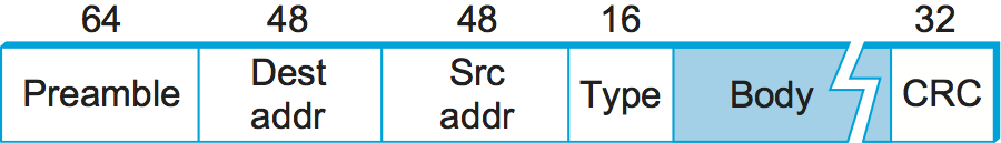
Figure 41. Ethernet frame format.
Addresses
Each host on an Ethernet—in fact, every Ethernet host in the world—has a
unique Ethernet address. Technically, the address belongs to the
adaptor, not the host; it is usually burned into ROM. Ethernet addresses
are typically printed in a form humans can read as a sequence of six
numbers separated by colons. Each number corresponds to 1 byte of the
6-byte address and is given by a pair of hexadecimal digits, one for
each of the 4-bit nibbles in the byte; leading 0s are dropped. For
example, 8:0:2b:e4:b1:2 is the human-readable representation of
Ethernet address
00001000 00000000 00101011 11100100 10110001 00000010
To ensure that every adaptor gets a unique address, each manufacturer of
Ethernet devices is allocated a different prefix that must be prepended
to the address on every adaptor they build. For example, Advanced Micro
Devices has been assigned the 24-bit prefix 080020 (or 8:0:20).
A given manufacturer then makes sure the address suffixes it produces
are unique.
Each frame transmitted on an Ethernet is received by every adaptor connected to that Ethernet. Each adaptor recognizes those frames addressed to its address and passes only those frames on to the host. (An adaptor can also be programmed to run in promiscuous mode, in which case it delivers all received frames to the host, but this is not the normal mode.) In addition to these unicast addresses, an Ethernet address consisting of all 1s is treated as a broadcast address; all adaptors pass frames addressed to the broadcast address up to the host. Similarly, an address that has the first bit set to 1 but is not the broadcast address is called a multicast address. A given host can program its adaptor to accept some set of multicast addresses. Multicast addresses are used to send messages to some subset of the hosts on an Ethernet (e.g., all file servers). To summarize, an Ethernet adaptor receives all frames and accepts
Frames addressed to its own address
Frames addressed to the broadcast address
Frames addressed to a multicast address, if it has been instructed to listen to that address
All frames, if it has been placed in promiscuous mode
It passes to the host only the frames that it accepts.
Transmitter Algorithm
As we have just seen, the receiver side of the Ethernet protocol is simple; the real smarts are implemented at the sender’s side. The transmitter algorithm is defined as follows.
When the adaptor has a frame to send and the line is idle, it transmits the frame immediately; there is no negotiation with the other adaptors. The upper bound of 1500 bytes in the message means that the adaptor can occupy the line for only a fixed length of time.
When an adaptor has a frame to send and the line is busy, it waits for the line to go idle and then transmits immediately. (To be more precise, all adaptors wait 9.6 μs after the end of one frame before beginning to transmit the next frame. This is true for both the sender of the first frame as well as those nodes listening for the line to become idle.) The Ethernet is said to be a 1-persistent protocol because an adaptor with a frame to send transmits with probability 1 whenever a busy line goes idle. In general, a p-persistent algorithm transmits with probability \(0 \le p \le 1\) after a line becomes idle and defers with probability q = 1 - p. The reasoning behind choosing a p<1 is that there might be multiple adaptors waiting for the busy line to become idle, and we don’t want all of them to begin transmitting at the same time. If each adaptor transmits immediately with a probability of, say, 33%, then up to three adaptors can be waiting to transmit and the odds are that only one will begin transmitting when the line becomes idle. Despite this reasoning, an Ethernet adaptor always transmits immediately after noticing that the network has become idle and has been very effective in doing so.
To complete the story about p-persistent protocols for the case when p<1, you might wonder how long a sender that loses the coin flip (i.e., decides to defer) has to wait before it can transmit. The answer for the Aloha network, which originally developed this style of protocol, was to divide time into discrete slots, with each slot corresponding to the length of time it takes to transmit a full frame. Whenever a node has a frame to send and it senses an empty (idle) slot, it transmits with probability p and defers until the next slot with probability q = 1 - p. If that next slot is also empty, the node again decides to transmit or defer, with probabilities p and q, respectively. If that next slot is not empty—that is, some other station has decided to transmit—then the node simply waits for the next idle slot and the algorithm repeats.
Returning to our discussion of the Ethernet, because there is no centralized control it is possible for two (or more) adaptors to begin transmitting at the same time, either because both found the line to be idle or because both had been waiting for a busy line to become idle. When this happens, the two (or more) frames are said to collide on the network. Each sender, because the Ethernet supports collision detection, is able to determine that a collision is in progress. At the moment an adaptor detects that its frame is colliding with another, it first makes sure to transmit a 32-bit jamming sequence and then stops the transmission. Thus, a transmitter will minimally send 96 bits in the case of a collision: 64-bit preamble plus 32-bit jamming sequence.
One way that an adaptor will send only 96 bits—which is sometimes called a runt frame—is if the two hosts are close to each other. Had the two hosts been farther apart, they would have had to transmit longer, and thus send more bits, before detecting the collision. In fact, the worst-case scenario happens when the two hosts are at opposite ends of the Ethernet. To know for sure that the frame it just sent did not collide with another frame, the transmitter may need to send as many as 512 bits. Not coincidentally, every Ethernet frame must be at least 512 bits (64 bytes) long: 14 bytes of header plus 46 bytes of data plus 4 bytes of CRC.
Why 512 bits? The answer is related to another question you might ask about an Ethernet: Why is its length limited to only 2500 m? Why not 10 or 1000 km? The answer to both questions has to do with the fact that the farther apart two nodes are, the longer it takes for a frame sent by one to reach the other, and the network is vulnerable to a collision during this time.
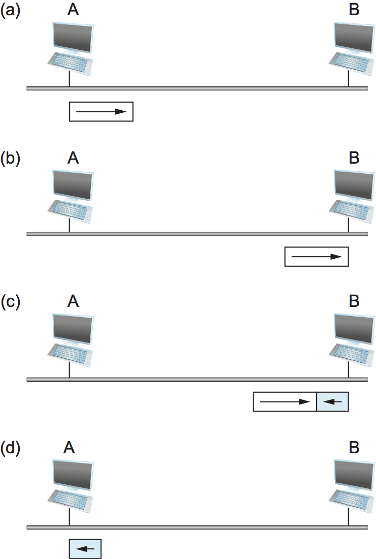
Figure 42. Worst-case scenario: (a) A sends a frame at time t; (b) A’s frame arrives at B at time t+d; (c) B begins transmitting at time t+d and collides with A’s frame; (d) B’s runt (32-bit) frame arrives at A at time t+2×d.
Figure 42 illustrates the worst-case scenario, where hosts A and B are at opposite ends of the network. Suppose host A begins transmitting a frame at time t, as shown in (a). It takes it one link latency (let’s denote the latency as d) for the frame to reach host B. Thus, the first bit of A’s frame arrives at B at time t+d, as shown in (b). Suppose an instant before host A’s frame arrives (i.e., B still sees an idle line), host B begins to transmit its own frame. B’s frame will immediately collide with A’s frame, and this collision will be detected by host B (c). Host B will send the 32-bit jamming sequence, as described above. (B’s frame will be a runt.) Unfortunately, host A will not know that the collision occurred until B’s frame reaches it, which will happen one link latency later, at time t+2×d, as shown in (d). Host A must continue to transmit until this time in order to detect the collision. In other words, host A must transmit for 2×d to be sure that it detects all possible collisions. Considering that a maximally configured Ethernet is 2500 m long, and that there may be up to four repeaters between any two hosts, the round-trip delay has been determined to be 51.2 μs, which on a 10-Mbps Ethernet corresponds to 512 bits. The other way to look at this situation is that we need to limit the Ethernet’s maximum latency to a fairly small value (e.g., 51.2 μs) for the access algorithm to work; hence, an Ethernet’s maximum length must be something on the order of 2500 m.
Once an adaptor has detected a collision and stopped its transmission, it waits a certain amount of time and tries again. Each time it tries to transmit but fails, the adaptor doubles the amount of time it waits before trying again. This strategy of doubling the delay interval between each retransmission attempt is a general technique known as exponential backoff. More precisely, the adaptor first delays either 0 or 51.2 μs, selected at random. If this effort fails, it then waits 0, 51.2, 102.4, or 153.6 μs (selected randomly) before trying again; this is k × 51.2 for k=0..3. After the third collision, it waits k × 51.2 for k = 0..23 - 1, again selected at random. In general, the algorithm randomly selects a k between 0 and 2n - 1 and waits k × 51.2 μs, where n is the number of collisions experienced so far. The adaptor gives up after a given number of tries and reports a transmit error to the host. Adaptors typically retry up to 16 times, although the backoff algorithm caps n in the above formula at 10.
2.6.3 Longevity of Ethernet
Ethernet has been the dominant local area network technology for over 30 years. Today it is typically deployed point-to-point rather than tapping into a coax cable, it often runs at speeds of 1 or 10 Gbps rather than 10 Mbps, and it allows jumbo packets with up to 9000 bytes of data rather than 1500 bytes. But, it remains backwards compatible with the original standard. This makes it worth saying a few words about why Ethernets have been so successful, so that we can understand the properties we should emulate with any technology that tries to replace it.
First, an Ethernet is extremely easy to administer and maintain: There is no routing or configuration tables to be kept up-to-date, and it is easy to add a new host to the network. It is hard to imagine a simpler network to administer. Second, it is inexpensive: cable/fiber is relatively cheap, and the only other cost is the network adaptor on each host. Ethernet became deeply entrenched for these reasons, and any switch-based approach that aspired to displace it required additional investment in infrastructure (the switches), on top of the cost of each adaptor. The switch-based variant of Ethernet did eventually succeed in replacing multi-access Ethernet, but this is primarily because it could be deployed incrementally—with some hosts connected by point-to-point links to switches while others remained tapped into coax and connected to repeaters or hubs—all the while retaining the simplicity of network administration.