4.3 Multicast
Multi-access networks like Ethernet implement multicast in hardware. There are, however, applications that need a broader multicasting capability that is effective at the scale of the Internet. For example, when a radio station is broadcast over the Internet, the same data must be sent to all the hosts where a user has tuned in to that station. In that example, the communication is one-to-many. Other examples of one-to-many applications include transmitting the same news, current stock prices, software updates, or TV channels to multiple hosts. The latter example is commonly called IPTV.
There are also applications whose communication is many-to-many, such as multimedia teleconferencing, online multiplayer gaming, or distributed simulations. In such cases, members of a group receive data from multiple senders, typically each other. From any particular sender, they all receive the same data.
Normal IP communication, in which each packet must be addressed and sent to a single host, is not well suited to such applications. If an application has data to send to a group, it would have to send a separate packet with the identical data to each member of the group. This redundancy consumes more bandwidth than necessary. Furthermore, the redundant traffic is not distributed evenly but rather is focused around the sending host, and may easily exceed the capacity of the sending host and the nearby networks and routers.
To better support many-to-many and one-to-many communication, IP provides an IP-level multicast analogous to the link-level multicast provided by multi-access networks like Ethernet. Now that we are introducing the concept of multicast for IP, we also need a term for the traditional one-to-one service of IP that has been described so far: That service is referred to as unicast.
The basic IP multicast model is a many-to-many model based on multicast groups, where each group has its own IP multicast address. The hosts that are members of a group receive copies of any packets sent to that group’s multicast address. A host can be in multiple groups, and it can join and leave groups freely by telling its local router using a protocol that we will discuss shortly. Thus, while we think of unicast addresses as being associated with a node or an interface, multicast addresses are associated with an abstract group, the membership of which changes dynamically over time. Further, the original IP multicast service model allows any host to send multicast traffic to a group; it doesn’t have to be a member of the group, and there may be any number of such senders to a given group.
Using IP multicast to send the identical packet to each member of the group, a host sends a single copy of the packet addressed to the group’s multicast address. The sending host doesn’t need to know the individual unicast IP address of each member of the group because, as we will see, that knowledge is distributed among the routers in the internetwork. Similarly, the sending host doesn’t need to send multiple copies of the packet because the routers will make copies whenever they have to forward the packet over more than one link. Compared to using unicast IP to deliver the same packets to many receivers, IP multicast is more scalable because it eliminates the redundant traffic (packets) that would have been sent many times over the same links, especially those near to the sending host.
IP’s original many-to-many multicast has been supplemented with support for a form of one-to-many multicast. In this model of one-to-many multicast, called Source-Specific Multicast (SSM), a receiving host specifies both a multicast group and a specific sending host. The receiving host would then receive multicasts addressed to the specified group, but only if they are from the specified sender. Many Internet multicast applications (e.g., radio broadcasts) fit the SSM model. To contrast it with SSM, IP’s original many-to-many model is sometimes referred to as Any Source Multicast (ASM).
A host signals its desire to join or leave a multicast group by communicating with its local router using a special protocol for just that purpose. In IPv4, that protocol is the Internet Group Management Protocol (IGMP); in IPv6, it is Multicast Listener Discovery (MLD). The router then has the responsibility for making multicast behave correctly with regard to that host. Because a host may fail to leave a multicast group when it should (after a crash or other failure, for example), the router periodically polls the network to determine which groups are still of interest to the attached hosts.
4.3.1 Multicast Addresses
IP has a subrange of its address space reserved for multicast addresses. In IPv4, these addresses are assigned in the class D address space, and IPv6 also has a portion of its address space reserved for multicast group addresses. Some subranges of the multicast ranges are reserved for intradomain multicast, so they can be reused independently by different domains.
There are thus 28 bits of possible multicast address in IPv4 when we ignore the prefix shared by all multicast addresses. This presents a problem when attempting to take advantage of hardware multicasting on a local area network (LAN). Let’s take the case of Ethernet. Ethernet multicast addresses have only 23 bits when we ignore their shared prefix. In other words, to take advantage of Ethernet multicasting, IP has to map 28-bit IP multicast addresses into 23-bit Ethernet multicast addresses. This is implemented by taking the low-order 23 bits of any IP multicast address to use as its Ethernet multicast address and ignoring the high-order 5 bits. Thus, 32 (25) IP addresses map into each one of the Ethernet addresses.
In this section we use Ethernet as a canonical example of a networking technology that supports multicast in hardware, but the same is also true of PON (Passive Optical Networks), which is the access network technology often used to deliver fiber-to-the-home. In fact, IP Multicast over PON is now a common way to deliver IPTV to homes.
When a host on an Ethernet joins an IP multicast group, it configures its Ethernet interface to receive any packets with the corresponding Ethernet multicast address. Unfortunately, this causes the receiving host to receive not only the multicast traffic it desired but also traffic sent to any of the other 31 IP multicast groups that map to the same Ethernet address, if they are routed to that Ethernet. Therefore, IP at the receiving host must examine the IP header of any multicast packet to determine whether the packet really belongs to the desired group. In summary, the mismatch of multicast address sizes means that multicast traffic may place a burden on hosts that are not even interested in the group to which the traffic was sent. Fortunately, in some switched networks (such as switched Ethernet) this problem can be mitigated by schemes wherein the switches recognize unwanted packets and discard them.
One perplexing question is how senders and receivers learn which multicast addresses to use in the first place. This is normally handled by out-of-band means, and there are some quite sophisticated tools to enable group addresses to be advertised on the Internet.
4.3.2 Multicast Routing (DVMRP, PIM, MSDP)
A router’s unicast forwarding tables indicate, for any IP address, which link to use to forward the unicast packet. To support multicast, a router must additionally have multicast forwarding tables that indicate, based on multicast address, which links—possibly more than one—to use to forward the multicast packet (the router duplicates the packet if it is to be forwarded over multiple links). Thus, where unicast forwarding tables collectively specify a set of paths, multicast forwarding tables collectively specify a set of trees: multicast distribution trees. Furthermore, to support Source-Specific Multicast (and, it turns out, for some types of Any Source Multicast), the multicast forwarding tables must indicate which links to use based on the combination of multicast address and the (unicast) IP address of the source, again specifying a set of trees.
Multicast routing is the process by which the multicast distribution trees are determined or, more concretely, the process by which the multicast forwarding tables are built. As with unicast routing, it is not enough that a multicast routing protocol “work”; it must also scale reasonably well as the network grows, and it must accommodate the autonomy of different routing domains.
DVMRP
Distance-vector routing used in unicast can be extended to support multicast. The resulting protocol is called Distance Vector Multicast Routing Protocol, or DVMRP. DVMRP was the first multicast routing protocol to see widespread use.
Recall that, in the distance-vector algorithm, each router maintains a
table of Destination, Cost, NextHop tuples, and exchanges a list of
(Destination, Cost) pairs with its directly connected neighbors.
Extending this algorithm to support multicast is a two-stage process.
First, we create a broadcast mechanism that allows a packet to be
forwarded to all the networks on the internet. Second, we need to refine
this mechanism so that it prunes back networks that do not have hosts
that belong to the multicast group. Consequently, DVMRP is one of
several multicast routing protocols described as flood-and-prune
protocols.
Given a unicast routing table, each router knows that the current
shortest path to a given destination goes through NextHop. Thus,
whenever it receives a multicast packet from source S, the router
forwards the packet on all outgoing links (except the one on which the
packet arrived) if and only if the packet arrived over the link that is
on the shortest path to S (i.e., the packet came from the NextHop
associated with S in the routing table). This strategy effectively
floods packets outward from S but does not loop packets back toward S.
There are two major shortcomings to this approach. The first is that it truly floods the network; it has no provision for avoiding LANs that have no members in the multicast group. We address this problem below. The second limitation is that a given packet will be forwarded over a LAN by each of the routers connected to that LAN. This is due to the forwarding strategy of flooding packets on all links other than the one on which the packet arrived, without regard to whether or not those links are part of the shortest-path tree rooted at the source.
The solution to this second limitation is to eliminate the duplicate broadcast packets that are generated when more than one router is connected to a given LAN. One way to do this is to designate one router as the parent router for each link, relative to the source, where only the parent router is allowed to forward multicast packets from that source over the LAN. The router that has the shortest path to source S is selected as the parent; a tie between two routers would be broken according to which router has the smallest address. A given router can learn if it is the parent for the LAN (again relative to each possible source) based upon the distance-vector messages it exchanges with its neighbors.
Notice that this refinement requires that each router keep, for each source, a bit for each of its incident links indicating whether or not it is the parent for that source/link pair. Keep in mind that in an internet setting, a source is a network, not a host, since an internet router is only interested in forwarding packets between networks. The resulting mechanism is sometimes called Reverse Path Broadcast (RPB) or Reverse Path Forwarding (RPF). The path is reverse because we are considering the shortest path toward the source when making our forwarding decisions, as compared to unicast routing, which looks for the shortest path to a given destination.
The RPB mechanism just described implements shortest-path broadcast. We now want to prune the set of networks that receives each packet addressed to group G to exclude those that have no hosts that are members of G. This can be accomplished in two stages. First, we need to recognize when a leaf network has no group members. Determining that a network is a leaf is easy—if the parent router as described above is the only router on the network, then the network is a leaf. Determining if any group members reside on the network is accomplished by having each host that is a member of group G periodically announce this fact over the network, as described in our earlier description of link-state multicast. The router then uses this information to decide whether or not to forward a multicast packet addressed to G over this LAN.
The second stage is to propagate this “no members of G here” information
up the shortest-path tree. This is done by having the router augment the
(Destination, Cost) pairs it sends to its neighbors with the set of
groups for which the leaf network is interested in receiving multicast
packets. This information can then be propagated from router to router,
so that for each of its links a given router knows for what groups it
should forward multicast packets.
Note that including all of this information in the routing update is a fairly expensive thing to do. In practice, therefore, this information is exchanged only when some source starts sending packets to that group. In other words, the strategy is to use RPB, which adds a small amount of overhead to the basic distance-vector algorithm, until a particular multicast address becomes active. At that time, routers that are not interested in receiving packets addressed to that group speak up, and that information is propagated to the other routers.
PIM-SM
Protocol Independent Multicast, or PIM, was developed in response to the scaling problems of earlier multicast routing protocols. In particular, it was recognized that the existing protocols did not scale well in environments where a relatively small proportion of routers want to receive traffic for a certain group. For example, broadcasting traffic to all routers until they explicitly ask to be removed from the distribution is not a good design choice if most routers don’t want to receive the traffic in the first place. This situation is sufficiently common that PIM divides the problem space into sparse mode and dense mode, where sparse and dense refer to the proportion of routers that will want the multicast. PIM dense mode (PIM-DM) uses a flood-and-prune algorithm like DVMRP and suffers from the same scalability problem. PIM sparse mode (PIM-SM) has become the dominant multicast routing protocol and is the focus of our discussion here. The “protocol independent” aspect of PIM, by the way, refers to the fact that, unlike earlier protocols such as DVMRP, PIM does not depend on any particular sort of unicast routing—it can be used with any unicast routing protocol, as we will see below.
In PIM-SM, routers explicitly join the multicast distribution tree using
PIM protocol messages known as Join messages. Note the contrast to
DVMRP’s approach of creating a broadcast tree first and then pruning the
uninterested routers. The question that arises is where to send those
Join messages because, after all, any host (and any number of hosts)
could send to the multicast group. To address this, PIM-SM assigns to
each group a special router known as the rendezvous point (RP). In
general, a number of routers in a domain are configured to be candidate
RPs, and PIM-SM defines a set of procedures by which all the routers in
a domain can agree on the router to use as the RP for a given group.
These procedures are rather complex, as they must deal with a wide
variety of scenarios, such as the failure of a candidate RP and the
partitioning of a domain into two separate networks due to a number of
link or node failures. For the rest of this discussion, we assume that
all routers in a domain know the unicast IP address of the RP for a
given group.
A multicast forwarding tree is built as a result of routers sending
Join messages to the RP. PIM-SM allows two types of trees to be
constructed: a shared tree, which may be used by all senders, and a
source-specific tree, which may be used only by a specific sending
host. The normal mode of operation creates the shared tree first,
followed by one or more source-specific trees if there is enough traffic
to warrant it. Because building trees installs state in the routers
along the tree, it is important that the default is to have only one
tree for a group, not one for every sender to a group.
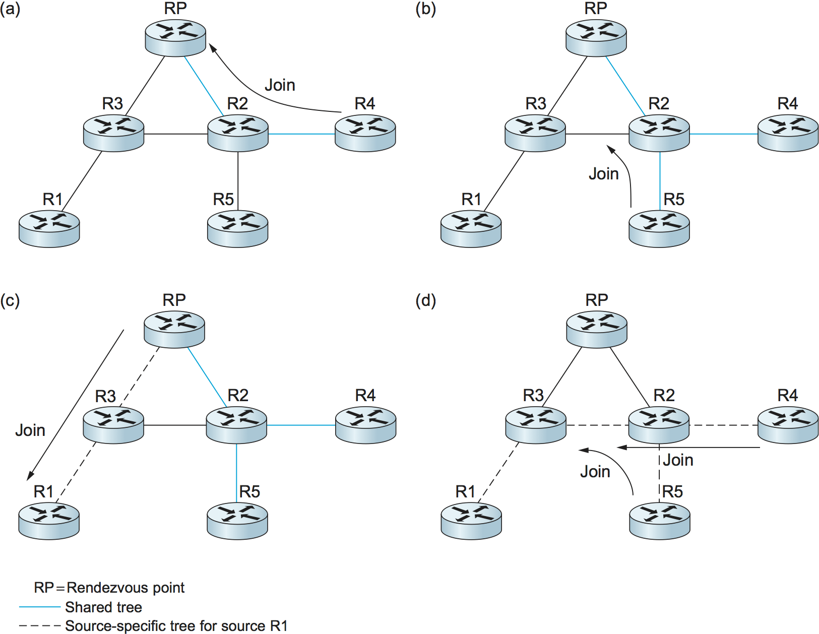
Figure 110. PIM operation: (a) R4 sends a Join message to RP and joins shared tree; (b) R5 joins shared tree; (c) RP builds source-specific tree to R1 by sending a Join message to R1; (d) R4 and R5 build source-specific tree to R1 by sending Join messages to R1.
When a router sends a Join message toward the RP for a group G, it
is sent using normal IP unicast transmission. This is illustrated in
Figure 110(a), in which router R4 is sending
a Join to the rendezvous point for some group. The initial
Join message is “wildcarded”; that is, it applies to all
senders. A Join message clearly must pass through some sequence of
routers before reaching the RP (e.g., R2). Each router along the path
looks at the Join and creates a forwarding table entry for the
shared tree, called a (*, G) entry (where * means “all senders”). To
create the forwarding table entry, it looks at the interface on which
the Join arrived and marks that interface as one on which it
should forward data packets for this group. It then determines which
interface it will use to forward the Join toward the RP. This will
be the only acceptable interface for incoming packets sent to this
group. It then forwards the Join toward the RP. Eventually, the
message arrives at the RP, completing the construction of the tree
branch. The shared tree thus constructed is shown as a solid line from
the RP to R4 in Figure 110(a).
As more routers send Joins toward the RP, they cause new branches
to be added to the tree, as illustrated in Figure
110(b). Note that, in this case, the Join only needs
to travel to R2, which can add the new branch to the tree simply by
adding a new outgoing interface to the forwarding table entry created
for this group. R2 need not forward the Join on to the RP. Note also
that the end result of this process is to build a tree whose root is the
RP.
At this point, suppose a host wishes to send a message to the
group. To do so, it constructs a packet with the appropriate multicast
group address as its destination and sends it to a router on its local
network known as the designated router (DR). Suppose the DR is R1 in
Figure 110. There is no state for this
multicast group between R1 and the RP at this point, so instead of
simply forwarding the multicast packet, R1 tunnels it to the
RP. That is, R1 encapsulates the multicast packet inside a PIM
Register message that it sends to the unicast IP address of the
RP. Just like an IP tunnel endpoint, the RP receives the packet
addressed to it, looks at the payload of the Register message, and
finds inside an IP packet addressed to the multicast address of this
group. The RP, of course, does know what to do with such a packet—it
sends it out onto the shared tree of which the RP is the root. In the
example of Figure 110, this means that the
RP sends the packet on to R2, which is able to forward it on to R4 and
R5. The complete delivery of a packet from R1 to R4 and R5 is shown in
Figure 111. We see the tunneled packet
travel from R1 to the RP with an extra IP header containing the
unicast address of RP, and then the multicast packet addressed to G
making its way along the shared tree to R4 and R5.
At this point, we might be tempted to declare success, since all hosts
can send to all receivers this way. However, there is some bandwidth
inefficiency and processing cost in the encapsulation and decapsulation
of packets on the way to the RP, so the RP forces knowledge about this
group into the intervening routers so tunneling can be avoided. It sends
a Join message toward the sending host (Figure
110(c)). As this Join travels toward the host, it
causes the routers along the path (R3) to learn about the group, so that
it will be possible for the DR to send the packet to the group as
native (i.e., not tunneled) multicast packets.
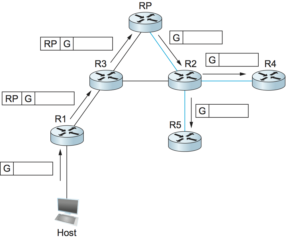
Figure 111. Delivery of a packet along a shared tree. R1 tunnels the packet to the RP, which forwards it along the shared tree to R4 and R5.
An important detail to note at this stage is that the Join message
sent by the RP to the sending host is specific to that sender, whereas
the previous ones sent by R4 and R5 applied to all senders. Thus, the
effect of the new Join is to create sender-specific state in the
routers between the identified source and the RP. This is referred to
as (S, G) state, since it applies to one sender to one group, and
contrasts with the (*, G) state that was installed between the
receivers and the RP that applies to all senders. Thus, in
Figure 110(c), we see a source-specific
route from R1 to the RP (indicated by the dashed line) and a tree that
is valid for all senders from the RP to the receivers (indicated by
the solid line).
The next possible optimization is to replace the entire shared tree
with a source-specific tree. This is desirable because the path from
sender to receiver via the RP might be significantly longer than the
shortest possible path. This again is likely to be triggered by a high
data rate being observed from some sender. In this case, the router at
the downstream end of the tree—say, R4 in our example—sends a
source-specific Join toward the source. As it follows the shortest
path toward the source, the routers along the way create (S, G) state
for this tree, and the result is a tree that has its root at the
source, rather than the RP. Assuming both R4 and R5 made the switch to
the source-specific tree, we would end up with the tree shown in
Figure 110(d). Note that this tree no longer
involves the RP at all. We have removed the shared tree from this
picture to simplify the diagram, but in reality all routers with
receivers for a group must stay on the shared tree in case new senders
show up.
We can now see why PIM is protocol independent. All of its mechanisms
for building and maintaining trees take advantage of unicast routing
without depending on any particular unicast routing protocol. The
formation of trees is entirely determined by the paths that Join
messages follow, which is determined by the choice of shortest paths
made by unicast routing. Thus, to be precise, PIM is “unicast routing
protocol independent,” as compared to DVMRP. Note that PIM is very much
bound up with the Internet Protocol—it is not protocol independent in
terms of network-layer protocols.
The design of PIM-SM again illustrates the challenges in building scalable networks and how scalability is sometimes pitted against some sort of optimality. The shared tree is certainly more scalable than a source-specific tree, in the sense that it reduces the total state in routers to be on the order of the number of groups rather than the number of senders times the number of groups. However, the source-specific tree is likely to be necessary to achieve efficient routing and effective use of link bandwidth.
Interdomain Multicast (MSDP)
PIM-SM has some significant shortcomings when it comes to interdomain multicast. In particular, the existence of a single RP for a group goes against the principle that domains are autonomous. For a given multicast group, all the participating domains would be dependent on the domain where the RP is located. Furthermore, if there is a particular multicast group for which a sender and some receivers shared a single domain, the multicast traffic would still have to be routed initially from the sender to those receivers via whatever domain has the RP for that multicast group. Consequently, the PIM-SM protocol is typically not used across domains, only within a domain.
To extend multicast across domains using PIM-SM, the Multicast Source Discovery Protocol (MSDP) was devised. MSDP is used to connect different domains—each running PIM-SM internally, with its own RPs—by connecting the RPs of the different domains. Each RP has one or more MSDP peer RPs in other domains. Each pair of MSDP peers is connected by a TCP connection over which the MSDP protocol runs. Together, all the MSDP peers for a given multicast group form a loose mesh that is used as a broadcast network. MSDP messages are broadcast through the mesh of peer RPs using the Reverse Path Broadcast algorithm that we discussed in the context of DVMRP.
What information does MSDP broadcast through the mesh of RPs? Not group
membership information; when a host joins a group, the furthest that
information will flow is its own domain’s RP. Instead, it is
source—multicast sender—information. Each RP knows the sources in its
own domain because it receives a Register message whenever a new
source arises. Each RP periodically uses MSDP to broadcast
Source Active messages to its peers, giving the IP address of the
source, the multicast group address, and the IP address of the
originating RP.

Figure 112. MSDP operation: (a) The source SR sends a Register message to its domain’s RP, RP1; then RP1 sends a source-specific Join message to SR and an MSDP Source Active message to its MSDP peer in Domain B, RP2; then RP2 sends a source-specific Join message to SR. (b) As a result, RP1 and RP2 are in the source-specific tree for source SR.
If an MSDP peer RP that receives one of these broadcasts has active
receivers for that multicast group, it sends a source-specific
Join, on that RP’s own behalf, to the source host, as shown in
Figure 112(a). The Join message builds a
branch of the source-specific tree to this RP, as shown in
Figure 112(b). The result is that every RP that
is part of the MSDP network and has active receivers for a particular
multicast group is added to the source-specific tree of the new
source. When an RP receives a multicast from the source, the RP uses
its shared tree to forward the multicast to the receivers in its
domain.
Source-Specific Multicast (PIM-SSM)
The original service model of PIM was, like earlier multicast protocols, a many-to-many model. Receivers joined a group, and any host could send to the group. However, it was recognized in the late 1990s that it might be useful to add a one-to-many model. Lots of multicast applications, after all, have only one legitimate sender, such as the speaker at a conference being sent over the Internet. We already saw that PIM-SM can create source-specific shortest path trees as an optimization after using the shared tree initially. In the original PIM design, this optimization was invisible to hosts—only routers joined source-specific trees. However, once the need for a one-to-many service model was recognized, it was decided to make the source-specific routing capability of PIM-SM explicitly available to hosts. It turns out that this mainly required changes to IGMP and its IPv6 analog, MLD, rather than PIM itself. The newly exposed capability is now known as PIM-SSM (PIM Source-Specific Multicast).
PIM-SSM introduces a new concept, the channel, which is the
combination of a source address S and a group address G. The group
address G looks just like a normal IP multicast address, and both IPv4
and IPv6 have allocated subranges of the multicast address space for
SSM. To use PIM-SSM, a host specifies both the group and the source in
an IGMP Membership Report message to its local router. That router then
sends a PIM-SM source-specific Join message toward the source,
thereby adding a branch to itself in the source-specific tree, just as
was described above for “normal” PIM-SM, but bypassing the whole
shared-tree stage. Since the tree that results is source specific, only
the designated source can send packets on that tree.
The introduction of PIM-SSM has provided some significant benefits, particularly since there is relatively high demand for one-to-many multicasting:
Multicasts travel more directly to receivers.
The address of a channel is effectively a multicast group address plus a source address. Therefore, given that a certain range of multicast group addresses will be used for SSM exclusively, multiple domains can use the same multicast group address independently and without conflict, as long as they use it only with sources in their own domains.
Because only the specified source can send to an SSM group, there is less risk of attacks based on malicious hosts overwhelming the routers or receivers with bogus multicast traffic.
PIM-SSM can be used across domains exactly as it is used within a domain, without reliance on anything like MSDP.
SSM, therefore, is quite a useful addition to the multicast service model.
Bidirectional Trees (BIDIR-PIM)
We round off our discussion of multicast with another enhancement to PIM known as Bidirectional PIM. BIDIR-PIM is a recent variant of PIM-SM that is well suited to many-to-many multicasting within a domain, especially when senders and receivers to a group may be the same, as in a multiparty videoconference, for example. As in PIM-SM, would-be receivers join groups by sending IGMP Membership Report messages (which must not be source specific), and a shared tree rooted at an RP is used to forward multicast packets to receivers. Unlike PIM-SM, however, the shared tree also has branches to the sources. That wouldn’t make any sense with PIM-SM’s unidirectional tree, but BIDIR-PIM’s trees are bidirectional—a router that receives a multicast packet from a downstream branch can forward it both up the tree and down other branches. The route followed to deliver a packet to any particular receiver goes only as far up the tree as necessary before going down the branch to that receiver. See the multicast route from R1 to R2 in Figure 113(b) for an example. R4 forwards a multicast packet downstream to R2 at the same time that it forwards a copy of the same packet upstream to R5.
A surprising aspect of BIDIR-PIM is that there need not actually be an
RP. All that is needed is a routable address, which is known as an RP
address even though it need not be the address of an RP or anything at
all. How can this be? A Join from a receiver is forwarded toward
the RP address until it reaches a router with an interface on the link
where the RP address would reside, where the Join
terminates. Figure 113(a) shows a Join
from R2 terminating at R5, and a Join from R3 terminating at
R6. The upstream forwarding of a multicast packet similarly flows
toward the RP address until it reaches a router with an interface on
the link where the RP address would reside, but then the router
forwards the multicast packet onto that link as the final step of
upstream forwarding, ensuring that all other routers on that link
receive the packet. Figure 113(b) illustrates
the flow of multicast traffic originating at R1.
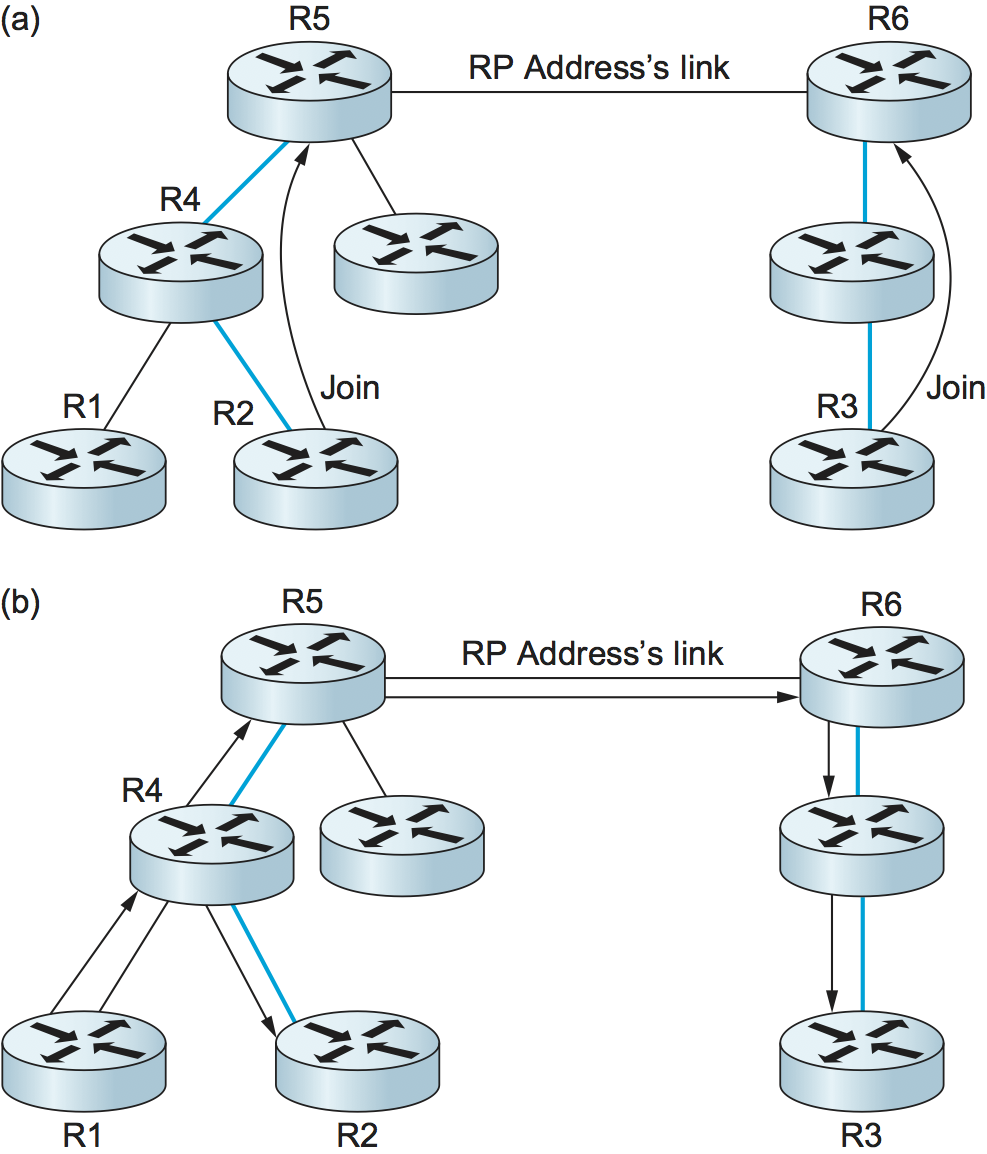
Figure 113. BIDIR-PIM operation: (a) R2 and R3 send Join messages toward the RP address that terminate when they reach a router on the RP address’s link. (b) A multicast packet from R1 is forwarded upstream to the RP address’s link and downstream wherever it intersects a group member branch.
BIDIR-PIM cannot thus far be used across domains. On the other hand, it has several advantages over PIM-SM for many-to-many multicast within a domain:
There is no source registration process because the routers already know how to route a multicast packet toward the RP address.
The routes are more direct than those that use PIM-SM’s shared tree because they go only as far up the tree as necessary, not all the way to the RP.
Bidirectional trees use much less state than the source-specific trees of PIM-SM because there is never any source-specific state. (On the other hand, the routes will be longer than those of source-specific trees.)
The RP cannot be a bottleneck, and indeed no actual RP is needed.
One conclusion to draw from the fact that there are so many different approaches to multicast just within PIM is that multicast is a difficult problem space in which to find optimal solutions. You need to decide which criteria you want to optimize (bandwidth usage, router state, path length, etc.) and what sort of application you are trying to support (one-to-many, many-to-many, etc.) before you can make a choice of the “best” multicast mode for the task.