5.4 Transport for Real-Time (RTP)
In the early days of packet switching, most applications were concerned with transferring files, although as early as 1981, experiments were under way to carry real-time traffic, such as digitized voice samples. We call an application “real-time” when it has strong requirements for the timely delivery of information. Voice over IP (VoIP) is a classic example of a real-time application because you can’t easily carry on a conversation with someone if it takes more than a fraction of a second to get a response. As we will see shortly, real-time applications place some specific demands on the transport protocol that are not well met by the protocols discussed so far in this chapter.
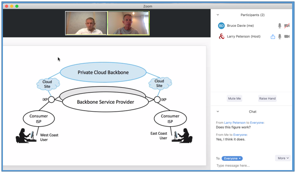
Figure 147. User interface of a videoconferencing tool.
Multimedia applications—those that involve video, audio, and data—are sometimes divided into two classes: interactive applications and streaming applications. Figure 147 shows the authors using an example conferencing tool that’s typical of the interactive class. Along with VoIP, these are the sort of applications with the most stringent real-time requirements.
Streaming applications typically deliver audio or video streams from a server to a client and are typified by such commercial products as Spotify. Streaming video, typified by YouTube and Netflix, has become one of the dominant forms of traffic on the Internet. Because streaming applications lack human-to-human interaction, they place somewhat less stringent real-time requirements on the underlying protocols. Timeliness is still important, however—for example, you want a video to start playing soon after pushing “play,” and once it starts to play, late packets will either cause it to stall or create some sort of visual degradation. So, while streaming applications are not strictly real time, they still have enough in common with interactive multimedia applications to warrant consideration of a common protocol for both types of application.
It should by now be apparent that designers of a transport protocol for real-time and multimedia applications face a real challenge in defining the requirements broadly enough to meet the needs of very different applications. They must also pay attention to the interactions among different applications, such as the synchronization of audio and video streams. We will see below how these concerns affected the design of the primary real-time transport protocol in use today: Real-time Transport Protocol (RTP).
Much of RTP actually derives from protocol functionality that was
originally embedded in the application itself. Two of the first such
applications were vic and vat, the former supporting real-time
video and the latter supporting real-time audio. Both applications
originally ran directly over UDP, while the designers figured out
which features were needed to handle the real-time nature of the
communication. Later, they realized that these features could be
useful to many other applications and defined a protocol with those
features. That protocol was eventually standardized as RTP.
RTP can run over many lower-layer protocols, but still commonly runs over UDP. That leads to the protocol stack shown in Figure 148. Note that we are therefore running a transport protocol over a transport protocol. There is no rule against that, and in fact it makes a lot of sense, since UDP provides such a minimal level of functionality, and the basic demultiplexing based on port numbers happens to be just what RTP needs as a starting point. So, rather than recreate port numbers in RTP, RTP outsources the demultiplexing function to UDP.
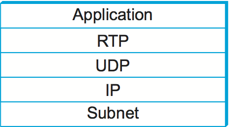
Figure 148. Protocol stack for multimedia applications using RTP.
5.4.1 Requirements
The most basic requirement for a general-purpose multimedia protocol is that it allows similar applications to interoperate with each other. For example, it should be possible for two independently implemented audioconferencing applications to talk to each other. This immediately suggests that the applications had better use the same method of encoding and compressing voice; otherwise, the data sent by one party will be incomprehensible to the receiving party. Since there are quite a few different coding schemes for voice, each with its own trade-offs among quality, bandwidth requirements, and computational cost, it would probably be a bad idea to decree that only one such scheme can be used. Instead, our protocol should provide a way that a sender can tell a receiver which coding scheme it wants to use, and possibly negotiate until a scheme that is available to both parties is identified.
Just as with audio, there are many different video coding schemes. Thus, we see that the first common function that RTP can provide is the ability to communicate that choice of coding scheme. Note that this also serves to identify the type of application (e.g., audio or video); once we know what coding algorithm is being used, we know what type of data is being encoded as well.
Another important requirement is to enable the recipient of a data stream to determine the timing relationship among the received data. Real-time applications need to place received data into a playback buffer to smooth out the jitter that may have been introduced into the data stream during transmission across the network. Thus, some sort of timestamping of the data will be necessary to enable the receiver to play it back at the appropriate time.
Related to the timing of a single media stream is the issue of synchronization of multiple media in a conference. The obvious example of this would be to synchronize an audio and video stream that are originating from the same sender. As we will see below, this is a slightly more complex problem than playback time determination for a single stream.
Another important function to be provided is an indication of packet loss. Note that an application with tight latency bounds generally cannot use a reliable transport like TCP because retransmission of data to correct for loss would probably cause the packet to arrive too late to be useful. Thus, the application must be able to deal with missing packets, and the first step in dealing with them is noticing that they are in fact missing. As an example, a video application using MPEG encoding may take different actions when a packet is lost, depending on whether the packet came from an I frame, a B frame, or a P frame.
Packet loss is also a potential indicator of congestion. Since multimedia applications generally do not run over TCP, they also miss out on the congestion avoidance features of TCP. Yet, many multimedia applications are capable of responding to congestion—for example, by changing the parameters of the coding algorithm to reduce the bandwidth consumed. Clearly, to make this work, the receiver needs to notify the sender that losses are occurring so that the sender can adjust its coding parameters.
Another common function across multimedia applications is the concept of frame boundary indication. A frame in this context is application specific. For example, it may be helpful to notify a video application that a certain set of packets correspond to a single frame. In an audio application it is helpful to mark the beginning of a “talkspurt,” which is a collection of sounds or words followed by silence. The receiver can then identify the silences between talkspurts and use them as opportunities to move the playback point. This follows the observation that slight shortening or lengthening of the spaces between words are not perceptible to users, whereas shortening or lengthening the words themselves is both perceptible and annoying.
A final function that we might want to put into the protocol is some way of identifying senders that is more user-friendly than an IP address. As illustrated in Figure 147, audio and video conferencing applications can display strings such as on their control panels, and thus the application protocol should support the association of such a string with a data stream.
In addition to the functionality that is required from our protocol, we note an additional requirement: It should make reasonably efficient use of bandwidth. Put another way, we don’t want to introduce a lot of extra bits that need to be sent with every packet in the form of a long header. The reason for this is that audio packets, which are one of the most common types of multimedia data, tend to be small, so as to reduce the time it takes to fill them with samples. Long audio packets would mean high latency due to packetization, which has a negative effect on the perceived quality of conversations. (This was one of the factors in choosing the length of ATM cells.) Since the data packets themselves are short, a large header would mean that a relatively large amount of link bandwidth would be used by headers, thus reducing the available capacity for “useful” data. We will see several aspects of the design of RTP that have been influenced by the necessity of keeping the header short.
You could argue whether every single feature just described really needs to be in a real-time transport protocol, and you could probably find some more that could be added. The key idea here is to make life easier for application developers by giving them a useful set of abstractions and building blocks for their applications. For example, by putting a timestamping mechanism into RTP, we save every developer of a real-time application from inventing his own. We also increase the chances that two different real-time applications might interoperate.
5.4.2 RTP Design
Now that we have seen the rather long list of requirements for our transport protocol for multimedia, we turn to the details of the protocol that has been specified to meet those requirements. This protocol, RTP, was developed in the IETF and is in widespread use. The RTP standard actually defines a pair of protocols, RTP and the Real-time Transport Control Protocol (RTCP). The former is used for the exchange of multimedia data, while the latter is used to periodically send control information associated with a certain data flow. When running over UDP, the RTP data stream and the associated RTCP control stream use consecutive transport-layer ports. The RTP data uses an even port number and the RTCP control information uses the next higher (odd) port number.
Because RTP is designed to support a wide variety of applications, it provides a flexible mechanism by which new applications can be developed without repeatedly revising the RTP protocol itself. For each class of application (e.g., audio), RTP defines a profile and one or more formats. The profile provides a range of information that ensures a common understanding of the fields in the RTP header for that application class, as will be apparent when we examine the header in detail. The format specification explains how the data that follows the RTP header is to be interpreted. For example, the RTP header might just be followed by a sequence of bytes, each of which represents a single audio sample taken a defined interval after the previous one. Alternatively, the format of the data might be much more complex; an MPEG-encoded video stream, for example, would need to have a good deal of structure to represent all the different types of information.
Key Takeaway
The design of RTP embodies an architectural principle known as Application Level Framing (ALF). This principle was put forward by Clark and Tennenhouse in 1990 as a new way to design protocols for emerging multimedia applications. They recognized that these new applications were unlikely to be well served by existing protocols such as TCP, and that furthermore they might not be well served by any sort of “one-size-fits-all” protocol. At the heart of this principle is the belief that an application understands its own needs best. For example, an MPEG video application knows how best to recover from lost frames and how to react differently if an I frame or a B frame is lost. The same application also understands best how to segment the data for transmission—for example, it’s better to send the data from different frames in different datagrams, so that a lost packet only corrupts a single frame, not two. It is for this reason that RTP leaves so many of the protocol details to the profile and format documents that are specific to an application. [Next]
Header Format
Figure 149 shows the header format used by RTP. The first 12 bytes are always present, whereas the contributing source identifiers are only used in certain circumstances. After this header there may be optional header extensions, as described below. Finally, the header is followed by the RTP payload, the format of which is determined by the application. The intention of this header is that it contain only the fields that are likely to be used by many different applications, since anything that is very specific to a single application would be more efficiently carried in the RTP payload for that application only.
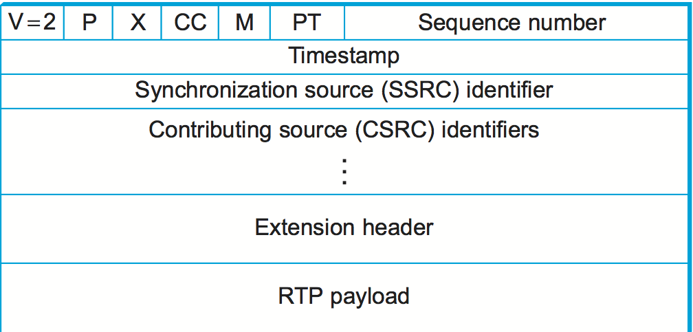
Figure 149. RTP header format.
The first two bits are a version identifier, which contains the value 2 in the RTP version deployed at the time of writing. You might think that the designers of the protocol were rather bold to think that 2 bits would be enough to contain all future versions of RTP, but recall that bits are at a premium in the RTP header. Furthermore, the use of profiles for different applications makes it less likely that many revisions to the base RTP protocol would be needed. In any case, if it turns out that another version of RTP is needed beyond version 2, it would be possible to consider a change to the header format so that more than one future version would be possible. For example, a new RTP header with the value 3 in the version field could have a “subversion” field somewhere else in the header.
The next bit is the padding (P) bit, which is set in
circumstances in which the RTP payload has been padded for some
reason. RTP data might be padded to fill up a block of a certain size
as required by an encryption algorithm, for example. In such a case,
the complete length of the RTP header, data, and padding would be
conveyed by the lower-layer protocol header (e.g., the UDP header),
and the last byte of the padding would contain a count of how many
bytes should be ignored. This is illustrated in Figure 150. Note that this approach to padding removes any need
for a length field in the RTP header (thus serving the goal of keeping
the header short); in the common case of no padding, the length is
deduced from the lower-layer protocol.
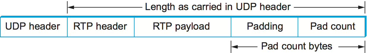
Figure 150. Padding of an RTP packet.
The extension (X) bit is used to indicate the presence of an
extension header, which would be defined for a specific application and
follow the main header. Such headers are rarely used, since it is
generally possible to define a payload-specific header as part of the
payload format definition for a particular application.
The X bit is followed by a 4-bit field that counts the number of
contributing sources, if any are included in the header. Contributing
sources are discussed below.
We noted above the frequent need for some sort of frame indication; this is provided by the marker bit, which has a profile-specific use. For a voice application, it could be set at the beginning of a talkspurt, for example. The 7-bit payload type field follows; it indicates what type of multimedia data is carried in this packet. One possible use of this field would be to enable an application to switch from one coding scheme to another based on information about resource availability in the network or feedback on application quality. The exact usage of the payload type is also determined by the application profile.
Note that the payload type is generally not used as a demultiplexing key to direct data to different applications (or to different streams within a single application, such as the audio and video stream for a videoconference). This is because such demultiplexing is typically provided at a lower layer (e.g., by UDP, as described in a previous section). Thus, two media streams using RTP would typically use different UDP port numbers.
The sequence number is used to enable the receiver of an RTP stream to detect missing and misordered packets. The sender simply increments the value by one for each transmitted packet. Note that RTP does not do anything when it detects a lost packet, in contrast to TCP, which both corrects for the loss (by retransmission) and interprets the loss as a congestion indication (which may cause it to reduce its window size). Rather, it is left to the application to decide what to do when a packet is lost because this decision is likely to be highly application dependent. For example, a video application might decide that the best thing to do when a packet is lost is to replay the last frame that was correctly received. Some applications might also decide to modify their coding algorithms to reduce bandwidth needs in response to loss, but this is not a function of RTP. It would not be sensible for RTP to decide that the sending rate should be reduced, as this might make the application useless.
The function of the timestamp field is to enable the receiver to play back samples at the appropriate intervals and to enable different media streams to be synchronized. Because different applications may require different granularities of timing, RTP itself does not specify the units in which time is measured. Instead, the timestamp is just a counter of “ticks,” where the time between ticks is dependent on the encoding in use. For example, an audio application that samples data once every 125 μs could use that value as its clock resolution. The clock granularity is one of the details that is specified in the RTP profile or payload format for an application.
The timestamp value in the packet is a number representing the time at which the first sample in the packet was generated. The timestamp is not a reflection of the time of day; only the differences between timestamps are relevant. For example, if the sampling interval is 125 μs and the first sample in packet n+1 was generated 10 ms after the first sample in packet n, then the number of sampling instants between these two samples is
TimeBetweenPackets / TimePerSample
= (10 × 10-3) / (125 × 10-6) = 80
Assuming the clock granularity is the same as the sampling interval, then the timestamp in packet n+1 would be greater than that in packet n by 80. Note that fewer than 80 samples might have been sent due to compression techniques such as silence detection, and yet the timestamp allows the receiver to play back the samples with the correct temporal relationship.
The synchronization source (SSRC) is a 32-bit number that uniquely identifies a single source of an RTP stream. In a given multimedia conference, each sender picks a random SSRC and is expected to resolve conflicts in the unlikely event that two sources pick the same value. By making the source identifier something other than the network or transport address of the source, RTP ensures independence from the lower-layer protocol. It also enables a single node with multiple sources (e.g., several cameras) to distinguish those sources. When a single node generates different media streams (e.g., audio and video), it is not required to use the same SSRC in each stream, as there are mechanisms in RTCP (described below) to allow intermedia synchronization.
The contributing source (CSRC) is used only when a number of RTP streams pass through a mixer. A mixer can be used to reduce the bandwidth requirements for a conference by receiving data from many sources and sending it as a single stream. For example, the audio streams from several concurrent speakers could be decoded and recoded as a single audio stream. In this case, the mixer lists itself as the synchronization source but also lists the contributing sources—the SSRC values of the speakers who contributed to the packet in question.
5.4.3 Control Protocol
RTCP provides a control stream that is associated with a data stream for a multimedia application. This control stream provides three main functions:
Feedback on the performance of the application and the network
A way to correlate and synchronize different media streams that have come from the same sender
A way to convey the identity of a sender for display on a user interface.
The first function may be useful for detecting and responding to congestion. Some applications are able to operate at different rates and may use performance data to decide to use a more aggressive compression scheme to reduce congestion, for example, or to send a higher-quality stream when there is little congestion. Performance feedback can also be useful in diagnosing network problems.
You might think that the second function is already provided by the synchronization source ID (SSRC) of RTP, but in fact it is not. As already noted, multiple cameras from a single node might have different SSRC values. Furthermore, there is no requirement that an audio and video stream from the same node use the same SSRC. Because collisions of SSRC values may occur, it may be necessary to change the SSRC value of a stream. To deal with this problem, RTCP uses the concept of a canonical name (CNAME) that is assigned to a sender, which is then associated with the various SSRC values that might be used by that sender using RTCP mechanisms.
Simply correlating two streams is only part of the problem of intermedia synchronization. Because different streams may have completely different clocks (with different granularities and even different amounts of inaccuracy, or drift), there needs to be a way to accurately synchronize streams with each other. RTCP addresses this problem by conveying timing information that correlates actual time of day with the clock-rate-dependent timestamps that are carried in RTP data packets.
RTCP defines a number of different packet types, including
Sender reports, which enable active senders to a session to report transmission and reception statistics
Receiver reports, which receivers who are not senders use to report reception statistics
Source descriptions, which carry CNAMEs and other sender description information
Application-specific control packets
These different RTCP packet types are sent over the lower-layer protocol, which, as we have noted, is typically UDP. Several RTCP packets can be packed into a single PDU of the lower-level protocol. It is required that at least two RTCP packets are sent in every lower-level PDU: One of these is a report packet; the other is a source description packet. Other packets may be included up to the size limits imposed by the lower-layer protocols.
Before looking further at the contents of an RTCP packet, we note that there is a potential problem with every member of a multicast group sending periodic control traffic. Unless we take some steps to limit it, this control traffic has the potential to be a significant consumer of bandwidth. In an audioconference, for example, no more than two or three senders are likely to send audio data at any instant, since there is no point in everyone talking at once. But there is no such social limit on everyone sending control traffic, and this could be a severe problem in a conference with thousands of participants. To deal with this problem, RTCP has a set of mechanisms by which the participants scale back their reporting frequency as the number of participants increases. These rules are somewhat complex, but the basic goal is this: Limit the total amount of RTCP traffic to a small percentage (typically 5%) of the RTP data traffic. To accomplish this goal, the participants should know how much data bandwidth is likely to be in use (e.g., the amount to send three audio streams) and the number of participants. They learn the former from means outside RTP (known as session management, discussed at the end of this section), and they learn the latter from the RTCP reports of other participants. Because RTCP reports might be sent at a very low rate, it might only be possible to get an approximate count of the current number of recipients, but that is typically sufficient. Also, it is recommended to allocate more RTCP bandwidth to active senders, on the assumption that most participants would like to see reports from them—for example, to find out who is speaking.
Once a participant has determined how much bandwidth it can consume with RTCP traffic, it sets about sending periodic reports at the appropriate rate. Sender reports and receiver reports differ only in that the former include some extra information about the sender. Both types of reports contain information about the data that was received from all sources in the most recent reporting period.
The extra information in a sender report consists of
A timestamp containing the actual time of day when this report was generated
The RTP timestamp corresponding to the time when the report was generated
Cumulative counts of the packets and bytes sent by this sender since it began transmission
Note that the first two quantities can be used to enable synchronization of different media streams from the same source, even if those streams use different clock granularities in their RTP data streams, since it gives the key to convert time of day to the RTP timestamps.
Both sender and receiver reports contain one block of data per source that has been heard from since the last report. Each block contains the following statistics for the source in question:
Its SSRC
The fraction of data packets from this source that were lost since the last report was sent (calculated by comparing the number of packets received with the number of packets expected; this last value can be determined from the RTP sequence numbers)
Total number of packets lost from this source since the first time it was heard from
Highest sequence number received from this source (extended to 32 bits to account for wrapping of the sequence number)
Estimated interarrival jitter for the source (calculated by comparing the interarrival spacing of received packets with the expected spacing at transmission time)
Last actual timestamp received via RTCP for this source
Delay since last sender report received via RTCP for this source
As you might imagine, the recipients of this information can learn all sorts of things about the state of the session. In particular, they can see if other recipients are getting much better quality from some sender than they are, which might be an indication that a resource reservation needs to be made, or that there is a problem in the network that needs to be attended to. In addition, if a sender notices that many receivers are experiencing high loss of its packets, it might decide that it should reduce its sending rate or use a coding scheme that is more resilient to loss.
The final aspect of RTCP that we will consider is the source
description packet. Such a packet contains, at a minimum, the SSRC of
the sender and the sender’s CNAME. The canonical name is derived in
such a way that all applications that generate media streams that
might need to be synchronized (e.g., separately generated audio and
video streams from the same user) will choose the same CNAME even
though they might choose different SSRC values. This enables a
receiver to identify the media stream that came from the same
sender. The most common format of the CNAME is user@host, where
host is the fully qualified domain name of the sending machine.
Thus, an application launched by the user whose user name is jdoe
running on the machine cicada.cs.princeton.edu would use the
string jdoe@cicada.cs.princeton.edu as its CNAME. The large and
variable number of bytes used in this representation would make it a
bad choice for the format of an SSRC, since the SSRC is sent with
every data packet and must be processed in real time. Allowing CNAMEs
to be bound to SSRC values in periodic RTCP messages enables a compact
and efficient format for the SSRC.
Other items may be included in the source description packet, such as the real name and email address of the user. These are used in user interface displays and to contact participants, but are less essential to the operation of RTP than the CNAME.
Like TCP, RTP and RTCP are a fairly complex pair of protocols. This complexity comes in large part from the desire to make life easier for application designers. Because there is an infinite number of possible applications, the challenge in designing a transport protocol is to make it general enough to meet the widely varying needs of many different applications without making the protocol itself impossible to implement. RTP has proven very successful in this regard, forming the basis for many real-time multimedia applications run over the Internet today.